GRID DIP OSCILLATOR by Harry Lythall - SM0VPO question


Page 1 of 2 • 1, 2 ![]()

Re: GRID DIP OSCILLATOR by Harry Lythall - SM0VPO question
![]() by Ivan Tue Dec 03, 2019 11:01 am
by Ivan Tue Dec 03, 2019 11:01 am
160 uA is another "cup of coffee". It probably is the own sensitivity of the Deprez system. Maybe it is not necessary to open the meter.
BR from Ivan
Ivan- Posts : 788
Join date : 2012-11-25
Age : 64
Location : Praha, Czechia
Re: GRID DIP OSCILLATOR by Harry Lythall - SM0VPO question
![]() by zsolt Mon Dec 02, 2019 9:46 pm
by zsolt Mon Dec 02, 2019 9:46 pm
i think the unit is uA not mA. I was on mA scale and i had 0.160 mA. Tomorrow i will look inside an measure. It has no units on just a blue line and a red line. When it was working i was told that at recording the line input potentiometer has to be adjusted in such way that the needle is always below red. I miss that magnetophone. It would have been a cool item in the house.
zsolt- Posts : 209
Join date : 2017-12-19
Re: GRID DIP OSCILLATOR by Harry Lythall - SM0VPO question
![]() by Ivan Mon Dec 02, 2019 7:17 pm
by Ivan Mon Dec 02, 2019 7:17 pm
Hi,zsolt wrote:I did found a needle meter from a russian magnetophone (Maiak). I did not see writing on it so i measured it. It takes 160mA to show full scale.
that seems too much current for a Deprez system! Maybe it has a shunt resistor inside. If it is so and you remove the shunt, the sensitivity will increase much. You certainly lose the calibration, if the meter had any.
VBR from Ivan
Ivan- Posts : 788
Join date : 2012-11-25
Age : 64
Location : Praha, Czechia
Re: GRID DIP OSCILLATOR by Harry Lythall - SM0VPO question
![]() by zsolt Mon Dec 02, 2019 4:01 pm
by zsolt Mon Dec 02, 2019 4:01 pm
i have no idea if 10 leds are enough. As a fsm now i have about 10mV /led and i could figure out what is happening to my 433MHz tx. The most gdo s on the net have 100mA indicator. In analogy with that the led display is about 100mV full scale. Don't know.
I did found a needle meter from a russian magnetophone (Maiak). I did not see writing on it so i measured it. It takes 160mA to show full scale. Probably i will use that instead and leave the led indicator as it is. For now the frequency's of interest are 8Mhz,13.5Mhz,(433Mhz)
zsolt- Posts : 209
Join date : 2017-12-19
Re: GRID DIP OSCILLATOR by Harry Lythall - SM0VPO question
![]() by admin Mon Dec 02, 2019 12:13 am
by admin Mon Dec 02, 2019 12:13 am
I have a couple of questions:
1 - Will an 10-LED bargraph give a good enough indication of a dip?
2 - As a FSM, there can be a really wide variation of signal strength. Again, will the 10-LED bar-graph be enought?
I once saw an article for an RTTY frequency meter, where four bar-graph chips were used to give a 40-step frequency display. They used the rectangular LEDs side-by-side to give a compact display.

The design even used the LED drivers to give a demodulation (5 LEDs for a MARK [1445Hz] and another 5 LEDs for a SPACE [1275Hz])
you could do the same with relative voltage :-)
BR Harry
_________________
Everything in this world is either bacon, or it isn't bacon
They say that money cannot bring you happiness, but if you have it then you can always buy more bacon

admin- Admin
- Posts : 1144
Join date : 2012-11-24
Age : 72
Location : Märsta, Sweden -

Re: GRID DIP OSCILLATOR by Harry Lythall - SM0VPO question
![]() by zsolt Sun Dec 01, 2019 10:32 am
by zsolt Sun Dec 01, 2019 10:32 am
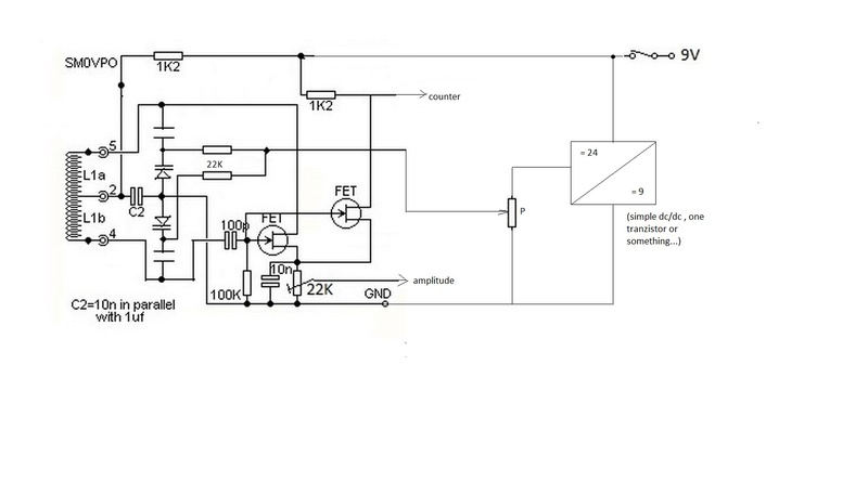
my morning coffee brought me a new idea. I thought to mix my new built rf meter with the GDO i plan to build.I imagine the pairing between the 2 like this

zsolt- Posts : 209
Join date : 2017-12-19
Re: GRID DIP OSCILLATOR by Harry Lythall - SM0VPO question
![]() by admin Sat Nov 30, 2019 10:48 pm
by admin Sat Nov 30, 2019 10:48 pm
Yes, he can see a bigger dipp.
The bridge cancels out the difference between the voltages in the two resistive paths. The balance gives zero volts. A more sensitive voltmeter can therefore give a bigger deflection in the voltmeter - he can see a bigger dipp
Best regards from him - Harry - SM0VPO
_________________
Everything in this world is either bacon, or it isn't bacon
They say that money cannot bring you happiness, but if you have it then you can always buy more bacon
admin- Admin
- Posts : 1144
Join date : 2012-11-24
Age : 72
Location : Märsta, Sweden -
Re: GRID DIP OSCILLATOR by Harry Lythall - SM0VPO question
![]() by zsolt Fri Nov 29, 2019 6:25 pm
by zsolt Fri Nov 29, 2019 6:25 pm
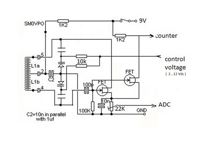
the following circuit keeps coming up

Why does he put the needle instrument in a bridge, can he see a bigger dipp?
{looks like i will be a specialist in this kind of analog circuits, now we have NFC & RFID labels)
zsolt- Posts : 209
Join date : 2017-12-19
Re: GRID DIP OSCILLATOR by Harry Lythall - SM0VPO question
![]() by admin Sun Jun 02, 2019 11:34 am
by admin Sun Jun 02, 2019 11:34 am
Sorry about this, but it should be a Field Effect Transistor
https://www.tme.eu/Document/6e680d4aba5c888ecb43931f06db6959/BF256B.pdf
I did state FET in the drawings, but did I give the wrong number? Should be BF256B (not BC256B).
I do apologise if I got it wrong.
Best regards from Harry - SM0VPO
_________________
Everything in this world is either bacon, or it isn't bacon
They say that money cannot bring you happiness, but if you have it then you can always buy more bacon
admin- Admin
- Posts : 1144
Join date : 2012-11-24
Age : 72
Location : Märsta, Sweden -
GDO 2
![]() by G0rnh Wed May 29, 2019 9:12 am
by G0rnh Wed May 29, 2019 9:12 am
I tried to build GDO 2 from your projects page. There appears to be a problem with the transistor number. You have mentioned BC256B. Is it correct? I am unable to make this circuit oscillate even after many assemblies. Please help.
G0rnh- Guest
Re: GRID DIP OSCILLATOR by Harry Lythall - SM0VPO question
![]() by admin Mon Mar 11, 2019 9:53 pm
by admin Mon Mar 11, 2019 9:53 pm
I have two grid dip meters, but if I had none then I would be tempted.
My 38-year old meter is still going strong, although the figures are not so easy to read. Perhaps I need to re-calibrate it?

It is still by for the best performing GDO I have ever used. My new one looks a lot neater, but the meter does dip a little when tuning the band(s).
Thank you for sharing the project. BR Harry - SM0VPO
_________________
Everything in this world is either bacon, or it isn't bacon
They say that money cannot bring you happiness, but if you have it then you can always buy more bacon
admin- Admin
- Posts : 1144
Join date : 2012-11-24
Age : 72
Location : Märsta, Sweden -
My Dipmeter
![]() by Branez Mon Mar 11, 2019 12:34 pm
by Branez Mon Mar 11, 2019 12:34 pm
Counter
Description on my website:
http://users.triera.net/zupanbra/drm/GDO-Eng.html#FET
At the moment I'm still waiting for PCBs from China. As soon as I get, I reported on My site an here.
_________________
Creativity is intelligence having fun!
Albert Einstein

Branez- Posts : 14
Join date : 2019-02-12
Age : 74
Location : Maribor, Slovenia -
Re: GRID DIP OSCILLATOR by Harry Lythall - SM0VPO question
![]() by admin Thu Jan 10, 2019 11:23 pm
by admin Thu Jan 10, 2019 11:23 pm
Sorry but I missed this massage.
The depth of the dip is determined by lots of parameters, for example:
- degree of coupling between oscillator and circuit under test
- Q-factor of the tuned circuit
- the impedance of the circuit under test
- the impedance of the GDO oscillator coil (yes, it does vary with frequency)
- any resistive losses or components that can load the circuit under test
In effect it is difficult to detect, but a very weak couopling gives the best accuracy. A tight coupling can cause the GDO to be pulled off frequency by the circuit under test.
BR Harry
_________________
Everything in this world is either bacon, or it isn't bacon
They say that money cannot bring you happiness, but if you have it then you can always buy more bacon
admin- Admin
- Posts : 1144
Join date : 2012-11-24
Age : 72
Location : Märsta, Sweden -
Re: GRID DIP OSCILLATOR by Harry Lythall - SM0VPO question
![]() by zsolt Sun Dec 16, 2018 10:50 pm
by zsolt Sun Dec 16, 2018 10:50 pm
why a DIP is not always with the same amplitude for different LC configurations on this circuit ?
I think about an algorithm to teach the microcomputer to find the DIP . The best thing i can think of is to set a threshold and at every iteration compare the measured level with that threshold. When the function returns the first lower or equal value then i am going to call that function again with a lower threshold . So when the function does not return a lower measured amplitude , that's the DIP at n-1 th iteration ....
zsolt- Posts : 209
Join date : 2017-12-19
Re: GRID DIP OSCILLATOR by Harry Lythall - SM0VPO question
![]() by zsolt Fri Mar 16, 2018 8:19 pm
by zsolt Fri Mar 16, 2018 8:19 pm

It was so simple in the end !
zsolt- Posts : 209
Join date : 2017-12-19
Re: GRID DIP OSCILLATOR by Harry Lythall - SM0VPO question
![]() by zsolt Tue Mar 13, 2018 7:11 pm
by zsolt Tue Mar 13, 2018 7:11 pm
i don't give up on the digitalised GDO , just that i have to delay that for now .
You remember the first GDO i ever bult from this site for testing security labels , somewhere in the first pages ?
Well it works ,we also bought a whole security gate to double check the labels and the "GDO label tester" , actually it works so well that "they" (where i work) want me to build an other GDO to send it to the Chinese so they can send us the labels we want . (i think if i send it there , in a week i can by it on e-bay or so, with free shipping
 )
) The thing is that i can't find double variable capacitor's (i could get some from the net but i also dislike them ) So i go with the varicap/zenner/led thing Using my experience with the digitalis-ed GDO attempt i made up the confusicus circuitus below

The main problem is the oscillogram i get in the scope (i forgot to take a picture but it looks like in the drawing)
It's in the Khz range , thous it's the replica of the digitalised version . Actually there i used 100pF with the zenners , here i put only 10 pf in the hope that frequency will go up to 8 MHz range
The level output i wanted to use for triggering (with an other circuit , trigger Schmidt ..or something i don't know yet... ) a LED for a good label that passes beside the coil . If i manage to make it to run good, i also intend to use a similar unit with trigger output to build a little sorter machine (unwind > nipp roll > GDO> rewind with a rudimentary tensioning system )
For now it is not oscillating right and i have no clue why, if you guys have an idea , that would help. I remember that the very first GDO put out a nice sine wave . It's not the zenners , i throw them out and put a 33 pf for each . Same form and same period . Oh and i also tried out LEDs instead of zenners . Leds are cool
zsolt- Posts : 209
Join date : 2017-12-19
Re: GRID DIP OSCILLATOR by Harry Lythall - SM0VPO question
![]() by zsolt Fri Mar 02, 2018 4:20 pm
by zsolt Fri Mar 02, 2018 4:20 pm
with the thin wire the f did go down... now i have an other trouble with the second fet. The drain signal is dc , about 6v with so little pulse that i can't see it . I managed to see it with the scope set on AC input

with this setting (the scope was working but for some reason the blitz completely erased the green line from the screen )

The signal looks like this (with the blitz off )

I took the source of the second fet and put it to ground . This increased somewhat the signal (in AC) about 800mV pp
I introduced one more tranzistor in the circuit

It's more complicated as i intended .... now i have frequency reading on LCD. . Just that changing voltage on the zenners does not affect frequency

zsolt- Posts : 209
Join date : 2017-12-19
Re: GRID DIP OSCILLATOR by Harry Lythall - SM0VPO question
![]() by admin Thu Mar 01, 2018 10:43 pm
by admin Thu Mar 01, 2018 10:43 pm
For "really" low frequencies I used the enamelled wire from relays. You can pile-wind then using an electric screwdriver, then it should bring the frequency down.
BR Harry
_________________
Everything in this world is either bacon, or it isn't bacon
They say that money cannot bring you happiness, but if you have it then you can always buy more bacon
admin- Admin
- Posts : 1144
Join date : 2012-11-24
Age : 72
Location : Märsta, Sweden -
Re: GRID DIP OSCILLATOR by Harry Lythall - SM0VPO question
![]() by zsolt Thu Mar 01, 2018 8:55 pm
by zsolt Thu Mar 01, 2018 8:55 pm
no need for that . It's oscillating alright , i discovered that it's on high frequency . It goes well above 100 Mhz . It's so out of my intended range that it's no use . I don't know yet how to build proper air wound coils to go down with frequency (or if it works like that )
Any way parts of the code are usable for other projects also. I tried to depict in a few lines what it does now. I intended to add a joystick to easily navigate through a little menu (also not donne) . If you read the little description you can see that you may theoretically use the frequency meter part for your projects at higher frequencies also just by tweaking the gate timer , but i can tell that the uc's electronic circuitry for some reason won't go higher than ~ 50 Mhz .
/*
* JAKAB ZSOLT 14.022018
* SOMETHING GDO like ... something
* LCD RS pin to digital pin 12
* LCD Enable pin to digital pin 11
* LCD D4 pin to digital pin 7
* LCD D5 pin to digital pin 4
* LCD D6 pin to digital pin 3
* LCD D7 pin to digital pin 2
* LCD R/W pin to ground
* LCD backlight control to pin 10
* boost PWM pin 6
* boost feedback pin A3
* dipp detection on A2
* timer one T1 input is port PD5 on the ATMEGA328P cip , that is in fact PIN 5 on ARDUINO NANO board , this will be the 2 byte counter register which can count up to 65536 .
* Timer two is used to provide the time base for gateing T1 counter's input . I used 1 ms gate time (for a frequency meter the user can make
* this parameter vaariable for better acuracy / autoscaling) , so the frequency is
* f = [ (65536 x number times that the register rolled over) + the register's acual value ] / 2000 [Mhz}
* The pid regulator is in paralell form , has self tuning included and uses 2 sets of P,I,D coeficients , one agressive set for large error and
* an other set for "close to zero error "
* I dont program a lot, because to layzy for that... many subroutines are borrowed and modified for my actual needs , it's not finished and is in a raw form . Fel free to use what u need ( as i did)
*/
#include <LiquidCrystal.h>
#include <PID_v1.h>
#include <avr/interrupt.h>
LiquidCrystal lcd(12, 11, 7, 4, 3, 2);
int dispcnt=0;
float refV=2.10;
double Setpoint, Input, Output; // PID vars
double aggKp=50, aggKi=1.7, aggKd=0.8;
double consKp=30, consKi=0.5, consKd=0.2;
double gap=0;
int btg=0;
unsigned char sreg;
byte smiley[8] = {
B00000,
B10001,
B00000,
B00000,
B10001,
B01110,
B00000,
};
volatile unsigned long period=0;
float frequency=0.00;
volatile boolean measurement_ready;
volatile unsigned char overflow_counter; // number of overflows within gate_time
volatile unsigned int time_so_far; // number of ISR calls
volatile unsigned int gate_time;
PID myPID(&Input, &Output, &Setpoint, consKp, consKi, consKd, DIRECT);
double CNT=0;
void setup()
{
delay(300);
pinMode(2, OUTPUT);
pinMode(3, OUTPUT);
pinMode(4, OUTPUT);
pinMode(5, INPUT);
pinMode(6, OUTPUT);
pinMode(7, OUTPUT);
pinMode(10, OUTPUT);
pinMode(11, OUTPUT);
pinMode(12, OUTPUT);
pinMode(A3, INPUT);
pinMode(A2, INPUT);
digitalWrite(10,1);
lcd.createChar(0, smiley);
lcd.begin(8, 2);
lcd.print("hello!");
lcd.setCursor(0,1);
lcd.write(" ");
lcd.write(byte(0));
delay(1000);
Setpoint = 2.5;
setPwmFrequency(6, 1); // 62500/1 = 62500 hz
Input = 2*(runningAverageFeedback(analogRead(A3)))*0.0049; // pid fedback
myPID.SetMode(AUTOMATIC); //turn the PID on
}
void loop()
{
Setpoint=2.01;
//__________________________________________________________
Input=14.1875*(runningAverageFeedback(analogRead(A3)))*0.0049;
gap = abs(Setpoint-Input); //distance away from setpoint
if (gap < 0.1)
{ //we're close to setpoint, use conservative tuning parameters
myPID.SetTunings(consKp, consKi, consKd);
}
else
{
//we're far from setpoint, use aggressive tuning parameters
myPID.SetTunings(aggKp, aggKi, aggKd);
}
myPID.Compute(); // run PID algorithm
if(Output>200)Output=200;
analogWrite(6,Output);
//____________________________________________________________
measurement(1); // 1 ms gate time
while (measurement_ready==false);
//________________________________________________________
dispcnt++;
if(dispcnt==250)
{
lcd.clear();
dispcnt=0;
lcd.print(Input,3);
lcd.setCursor(0,1);
lcd.print(frequency,3);
if(frequency<10)lcd.write(" ");
if(frequency>=10 && frequency<=100)lcd.write(" ");
lcd.write('M');
}
}
//______________________________________________________
long runningAverageFeedback(int M) {
#define LM_SIZE 18
static int LM[LM_SIZE];
static byte index = 0;
static long sum = 0;
static byte count = 0;
sum -= LM[index];
LM[index] = M;
sum += LM[index];
index++;
index = index % LM_SIZE;
if (count < LM_SIZE) count++;
return sum / count;
}
//---------------------------------------------------------------
void setPwmFrequency(int pin, int divisor) {
byte mode;
if(pin == 5 || pin == 6 || pin == 9 || pin == 10) {
switch(divisor) {
case 1: mode = 0x01; break;
case 8: mode = 0x02; break;
case 64: mode = 0x03; break;
case 256: mode = 0x04; break;
case 1024: mode = 0x05; break;
default: return;
}
if(pin == 5 || pin == 6) {
TCCR0B = TCCR0B & 0b11111000 | mode;
} else {
TCCR1B = TCCR1B & 0b11111000 | mode;
}
} else if(pin == 3 || pin == 11) {
switch(divisor) {
case 1: mode = 0x01; break;
case 8: mode = 0x02; break;
case 32: mode = 0x03; break;
case 64: mode = 0x04; break;
case 128: mode = 0x05; break;
case 256: mode = 0x06; break;
case 1024: mode = 0x07; break;
default: return;
}
TCCR2B = TCCR2B & 0b11111000 | mode;
}
}
//_______________________________________________________________
void measurement(int ms) {
bitClear(TIMSK0,TOIE0); // disable counter0 in order to disable millis() and delay()
// this will prevent extra interrupts that disturb the measurement
delayMicroseconds(66); // wait for other interrupts to finish
gate_time=ms; // usually 1000 (ms)
// setup of counter 1 which will be used for counting the signal impulses
TCCR1A=0; // reset timer/counter1 control register A
TCCR1B=0; // reset timer/counter1 control register B
TCCR2A=0; // reset timer/counter1 control register A
TCCR2B=0; // reset timer/counter2 control register A
// setup of counter2 which will be used to create an interrupt every millisecond (used for gate time)
TCCR2B |= B00000101; // set prescale factor of counter2 to 128 (16MHz/128 = 125000Hz)
// by setting CS22=1, CS21=0, CS20=1
bitSet(TCCR2A,WGM21) ; // set counter2 to CTC mode
// WGM22=0, WGM21=1, WGM20=0
OCR2A = 124; // CTC divider will divide 125Kz by 125
measurement_ready=0; // reset
time_so_far=0; // reset
bitSet(GTCCR,PSRASY); // reset the prescaler
TCNT1=0; // set frequency counter1 to 0
TCNT2=0; // set gate time counter2 to 0
bitSet(TIMSK2,OCIE2A); // enable counter2 interrupts
TCCR1B |= B00000111; // set CS12, CS11 and CS10 to "1" which starts counting
// on T1 pin (Arduino pin D5)
}
//_______________________________________________________________________________________________________
ISR(TIMER2_COMPA_vect) {
if (time_so_far >= gate_time) { // end of gate time, measurement is ready
TCCR1B &= B11111000; // stop counter1 by setting CS12, CS11 and CS10 to "0"
period=0x10000 * overflow_counter; // mult #overflows by 65636 (0x10000)
period += TCNT1; // add counter1 contents for final value
frequency = (float)period/2000; // frequency [Mhz]
overflow_counter=0; // reset overflow counter
bitClear(TIMSK2,OCIE2A); // disable counter2 interrupts
bitSet(TIMSK0,TOIE0); // enable Timer0 again // millis and delay
measurement_ready=true; // set global flag for end count period
}
else {
time_so_far++; // count number of interrupt events
if bitRead(TIFR1,TOV1) { // if Timer/Counter 1 overflow flag = "1" then ...
overflow_counter++; // increase number of counter1 overflows
bitSet(TIFR1,TOV1); // reset counter1 overflow flag
}
};
}
zsolt- Posts : 209
Join date : 2017-12-19
Re: GRID DIP OSCILLATOR by Harry Lythall - SM0VPO question
![]() by admin Wed Feb 28, 2018 9:13 pm
by admin Wed Feb 28, 2018 9:13 pm
I would expect the frequency to increase when you use varicap/zeners, maybe 5x the frequency, but this circuit usually oscillates so easily.
BR Harry
_________________
Everything in this world is either bacon, or it isn't bacon
They say that money cannot bring you happiness, but if you have it then you can always buy more bacon
admin- Admin
- Posts : 1144
Join date : 2012-11-24
Age : 72
Location : Märsta, Sweden -
Re: GRID DIP OSCILLATOR by Harry Lythall - SM0VPO question
![]() by zsolt Wed Feb 28, 2018 8:04 am
by zsolt Wed Feb 28, 2018 8:04 am
i removed the zenners , added the 15pF changed the BF245 with BF256 , same result.
Usually when i build an amplifier i get a wonderful oscillator.
I think it might oscillate , i put on a 10 Mhz osciloscope . It does show a very high frequency signal , actually i can receive that with fm radio on 98Mhz .
That's bad i wanted a frequency range to be maximum 10 Mhz .
if i put back the zenners the signal is gone .
And also no matter what capacitor i put instead of the zenner the signal is same , after capacitor increase, above 1nF the signal is gone .
zsolt- Posts : 209
Join date : 2017-12-19
Re: GRID DIP OSCILLATOR by Harry Lythall - SM0VPO question
![]() by admin Tue Feb 27, 2018 10:56 pm
by admin Tue Feb 27, 2018 10:56 pm
Remove the Zener diodes and fit 15pf capacitors. Check if it oscillates then:
If it does oscillate then make sure you have the zeners the correct way round (DC volts across them, with +ve to cathode).
If it does NOT oscillate then you have a basic oscillator problem (wiring or defect device).
Assuming you have checked the circuit is correctly wired ?
BR Harry
_________________
Everything in this world is either bacon, or it isn't bacon
They say that money cannot bring you happiness, but if you have it then you can always buy more bacon
admin- Admin
- Posts : 1144
Join date : 2012-11-24
Age : 72
Location : Märsta, Sweden -
Re: GRID DIP OSCILLATOR by Harry Lythall - SM0VPO question
![]() by zsolt Tue Feb 27, 2018 7:40 pm
by zsolt Tue Feb 27, 2018 7:40 pm
i put last parts on , fire it up and .... it's not oscillating

zsolt- Posts : 209
Join date : 2017-12-19
Re: GRID DIP OSCILLATOR by Harry Lythall - SM0VPO question
![]() by admin Tue Feb 27, 2018 3:36 am
by admin Tue Feb 27, 2018 3:36 am
The varicap-zener still gives you good capacitance ratio, so you can still have a reasonable frequency ratio - just a higher freq. range than the variable caps, thats all.
BR Harry
_________________
Everything in this world is either bacon, or it isn't bacon
They say that money cannot bring you happiness, but if you have it then you can always buy more bacon
admin- Admin
- Posts : 1144
Join date : 2012-11-24
Age : 72
Location : Märsta, Sweden -
Re: GRID DIP OSCILLATOR by Harry Lythall - SM0VPO question
![]() by zsolt Mon Feb 26, 2018 9:25 pm
by zsolt Mon Feb 26, 2018 9:25 pm
hmm , so i could estimate max zenner capacitance about 30 pF ... if i put 33pF for the fix capacitors in the end it would be really high frequency . Maybe i can take it down around 8 Mhz with the coil ..Admin wrote:The 16-V Zener has a capacitance of about 15pf at 2 volts, at least those I tried did.
LEDs also work as varicaps, but the capacitance is a little less and they seem to fail at higher frequencies (above 200MHz).
Good luck with the zeners.
BR Harry
zsolt- Posts : 209
Join date : 2017-12-19
Re: GRID DIP OSCILLATOR by Harry Lythall - SM0VPO question
![]() by admin Mon Feb 26, 2018 9:14 pm
by admin Mon Feb 26, 2018 9:14 pm
LEDs also work as varicaps, but the capacitance is a little less and they seem to fail at higher frequencies (above 200MHz).
Good luck with the zeners.
BR Harry
_________________
Everything in this world is either bacon, or it isn't bacon
They say that money cannot bring you happiness, but if you have it then you can always buy more bacon
admin- Admin
- Posts : 1144
Join date : 2012-11-24
Age : 72
Location : Märsta, Sweden -
Re: GRID DIP OSCILLATOR by Harry Lythall - SM0VPO question
![]() by zsolt Mon Feb 26, 2018 8:35 pm
by zsolt Mon Feb 26, 2018 8:35 pm
Admin wrote:It is looking good.
I am sorry but I don't have any 24-V Zener diodes or I would willingly send you a few.
It will be interesting to see how your unit works. Please keep us informed :-)
BR Harry
I can purchase everything from tme.eu what the local supplier don't has that's not a problem just that the shipment is from week to week , on Friday s (younger papanasos don't have patience )
I have bought several zenners , i put there 2 of 24 V .
I also have capacitors from 33pF to 470 pF. I don't know how to estimate the zenners capacitance . I know that with 2 series capacitor connection the equivalent is smaller than the smaller from both . Should i put there 100pF and see what happens ?
Or maybe 330pF ? if the zenner can go up to 330pF , than Cmax vould be ~165 pf and Cmin a little lower than the zenner can go , All most like the variable condensator u used .
zsolt- Posts : 209
Join date : 2017-12-19
Re: GRID DIP OSCILLATOR by Harry Lythall - SM0VPO question
![]() by admin Mon Feb 26, 2018 7:20 pm
by admin Mon Feb 26, 2018 7:20 pm
I am sorry but I don't have any 24-V Zener diodes or I would willingly send you a few.
It will be interesting to see how your unit works. Please keep us informed :-)
BR Harry
_________________
Everything in this world is either bacon, or it isn't bacon
They say that money cannot bring you happiness, but if you have it then you can always buy more bacon
admin- Admin
- Posts : 1144
Join date : 2012-11-24
Age : 72
Location : Märsta, Sweden -
Re: GRID DIP OSCILLATOR by Harry Lythall - SM0VPO question
![]() by zsolt Sun Feb 25, 2018 5:00 pm
by zsolt Sun Feb 25, 2018 5:00 pm

I don't keep many spare discrete components in stock . I need to buy two 24 V zenners as varicap diodes and the dc blocking capacitor for them . What would be a reasonable range for them ? 33pF ...100 pF ?
This i have on the board now + uncertainties

zsolt- Posts : 209
Join date : 2017-12-19
Re: GRID DIP OSCILLATOR by Harry Lythall - SM0VPO question
![]() by admin Wed Feb 21, 2018 8:57 pm
by admin Wed Feb 21, 2018 8:57 pm
If you have files to add then I can host them for you. Just send me the files.
I also think it must be possible to create anb HTML server where guests can post pix and files, then link to them in the forum.
Hmmm ... maybe the facility already exists ... will cheque.
BR Harry
_________________
Everything in this world is either bacon, or it isn't bacon
They say that money cannot bring you happiness, but if you have it then you can always buy more bacon
admin- Admin
- Posts : 1144
Join date : 2012-11-24
Age : 72
Location : Märsta, Sweden -
Re: GRID DIP OSCILLATOR by Harry Lythall - SM0VPO question
![]() by zsolt Tue Feb 20, 2018 7:56 pm
by zsolt Tue Feb 20, 2018 7:56 pm
ok , i'll need some help with the code thing , in principle i can copy / paste it here . But i'm using some header files and libraries pre-installed on my computer. So it wont be usable so directly as it is , one must download libraries i also downloaded and add them to it's own library director on C: Program files/ Arduino / libraries....... (the boring stuff..) . Anyway one can post here questions so it should not be a problem helping outAdmin wrote:Yes, you must keep us informed. Code would be really appreciated.
As regards tubes, I am having a little nostalgia at the moment with tubes. I have the circuit of my oscilloscope to document, sitting here on paper awaiting to be drawn. Things to do every day :-)
Will post the circuits as soon as they are drawn and viewed.
BR Harry
Working with these little useful boards is so easy , there are hundreds of examples on ''holly google" for absolutely everything , every module or peripheric once invented and available on the market . I discovered these boards a few years ago and i started to integrate them in industrial equipment . I can tell that in some particular cases (small and simple applications, not so fast processes ) they can successfully replace an expensive PLC . (not to mention that programming doesn't need more than an USB cable )
Before them i was working with microcontrollers from microchip, i may still have some useful circuits for you radio amateurs that i can share , actually things i use some times , frequency meter , L C meter (i think this was probably made by a radio amateur because of the small values it can measure
zsolt- Posts : 209
Join date : 2017-12-19
Re: GRID DIP OSCILLATOR by Harry Lythall - SM0VPO question
![]() by admin Tue Feb 20, 2018 9:59 am
by admin Tue Feb 20, 2018 9:59 am
As regards tubes, I am having a little nostalgia at the moment with tubes. I have the circuit of my oscilloscope to document, sitting here on paper awaiting to be drawn. Things to do every day :-)
Will post the circuits as soon as they are drawn and viewed.
BR Harry
_________________
Everything in this world is either bacon, or it isn't bacon
They say that money cannot bring you happiness, but if you have it then you can always buy more bacon
admin- Admin
- Posts : 1144
Join date : 2012-11-24
Age : 72
Location : Märsta, Sweden -
Re: GRID DIP OSCILLATOR by Harry Lythall - SM0VPO question
![]() by zsolt Mon Feb 19, 2018 7:02 pm
by zsolt Mon Feb 19, 2018 7:02 pm
Oh and i have a box full with valves , when i will have time to play, i think i will build something around here , maybe a radio
zsolt- Posts : 209
Join date : 2017-12-19
Re: GRID DIP OSCILLATOR by Harry Lythall - SM0VPO question
![]() by admin Sun Feb 18, 2018 9:59 pm
by admin Sun Feb 18, 2018 9:59 pm
It gives me a great thrill when someone can take one of my projects and "run with it".
Please DO keep the photo's coming. I would also be interested in a final "circuitus-diagramus confusicus" when it is finished.
Small comment about frequency range, there is absolutely no reason why you cannot use more coils to cover a wider range.
Another project I will phograph when I return to Sweden is a Tunnel-Diode oscillator. In principle it is two resistors, one capacitor and a 9-volt battery. If you connect the two crocodile clips to anything that resonates then it will oscillate at that thing's resonant frequency.
In my courses I connect it to a roll of URM67-U cable (with the far end shorted) and switch it on. It always oscillates at 1.1210MHz, because the cable length is 88.314 metres. I use a counter or a spectrum analyser to view the frequency.
This could be an altrernative to the GDO and may well work in your application. Pruning antenna centre-frequencies, coil resonance, cable resonance, cable-length ...
BT Harry - SM0VPO
_________________
Everything in this world is either bacon, or it isn't bacon
They say that money cannot bring you happiness, but if you have it then you can always buy more bacon
admin- Admin
- Posts : 1144
Join date : 2012-11-24
Age : 72
Location : Märsta, Sweden -
Re: GRID DIP OSCILLATOR by Harry Lythall - SM0VPO question
![]() by zsolt Sun Feb 18, 2018 9:58 am
by zsolt Sun Feb 18, 2018 9:58 am

first row now is a voltage .
second row is frequency . I used a small dds signal generator i have (has only 0-65khz, and a few Mhz @ ttl level) to generate some signal
Also at the moment the circuit looks like this

Voltage feedback (first row, set point being 12V) on pin A3 is the input of a discrete PID controller and pin 6 is it's output (Fpwm =65kHz). Frequency is counted by timer T1 configured as external clock sourced counter (pin 5) and internal timer 2 is used as 1ms gate for T1.
The boost converter need's some proper corrections (i used what i found) thous its behaving well thanks to the control algorithm , it still draws ~ 70 mA at full range 48 V (12 V on output) for doing nothing (perhaps only for charging the 10uF and supplying the voltage divider circuits ?? )
The whole thing takes 100mA
zsolt- Posts : 209
Join date : 2017-12-19
Re: GRID DIP OSCILLATOR by Harry Lythall - SM0VPO question
![]() by zsolt Thu Feb 15, 2018 10:16 pm
by zsolt Thu Feb 15, 2018 10:16 pm
i seee ...
Now i just put together the boost converter, arduno and lcd . In first place i'll try to write a little program to see on lcd the voltage regulation for the varicaps . I'm using a PID regulator to control voltage . For the moment i close the PID loop with a voltage feedback . For the non linearity you mentioned i just came up with an other idea , in the end when things work a little bit i just have to close the PID loop feedback on the frequency reading instead of the voltage reading i'm doing now , so it's up to the PID to deal with the voltage
I will show up with some pictures when i put something presentable together .
At the moment i have some trouble with finding an adequate coil for the boost converter . I should have build the coil winder i wanted (and learn how to calculate coils for dc-dc converters )
I found an online boost calculator which gives me an approximation of the coil i need . The closest store doesn't supply coils at all (except for big audio filter coils), i also throw away electronic scrap around the house ... this will take a while
zsolt- Posts : 209
Join date : 2017-12-19
Re: GRID DIP OSCILLATOR by Harry Lythall - SM0VPO question
![]() by Ivan Thu Feb 15, 2018 9:51 am
by Ivan Thu Feb 15, 2018 9:51 am
Hi,zsolt wrote:HI ,
I don't understand the term 3:1 frequency ratio , also 9:1 capacitance ratio . The ratio of f1/f2 = 3 , and C1/C2=9 ? If so what is f1,f2,C1,C2 ?
f1 ... the lowest frequency of the range
f2 ... the highest frequency
C1 ... maximum capacity
C2 ... minimum capacity
The frequency is inversely proportional to the square root of capacity, so to get a 3:1 frequency ratio, you need a 9:1 capacity ratio with fixed inductance.
BTW, the dependance of diode capacity on DC voltage is very nonlinear, too. If you want to optimize the frequency search, you should use various voltage steps at different parts of the range.
BR from Ivan OK1SIP
Ivan- Posts : 788
Join date : 2012-11-25
Age : 64
Location : Praha, Czechia
Re: GRID DIP OSCILLATOR by Harry Lythall - SM0VPO question
![]() by zsolt Wed Feb 14, 2018 8:01 pm
by zsolt Wed Feb 14, 2018 8:01 pm
HI ,Admin wrote:Hi Zsolt,
The varicaps should not draw any current at all.
I also once read that you can use switching diodes to get a really wide frequency ratio. To get 3:1 frequency you need at least 9:1 capacitance raio. Using an ordinary 1N914 switching diode you can bias it to a specific voltage.
When the oscillations cause the RF waveform in the oscillator, the diode will conduct for only a part of the RF sine waveform, and switch in a bigger capacitor for only a part of the waveform. If you have trouble with frequency range then this could be a solution.Also cheap diodes, not varicaps.
BR Harry - SM0VPO
I don't understand the term 3:1 frequency ratio , also 9:1 capacitance ratio . The ratio of f1/f2 = 3 , and C1/C2=9 ? If so what is f1,f2,C1,C2 ?
Oh and one other thing , what f/V ratio would be adequate to start with ? I'm just concerning that if the voltage increment is to big, the frequency variation is to large ... I can express myself better like this : should i hunt for Vout=Vout+0.1 ; or Vout = Vout+0.001 increments ? (since frequency is function of Vout i think this is important)
Maybe a big range can be covered with one single coil using these varicaps , this would be also a thing to hunt for
First i'm going to build the boost converter with the arduino and an lcd to test the voltage regulation capability . Also the arduino's counter can't go higher than ~60 Mhz so this is also a limit . I read about some simple counter IC's that can be used to divide by 2 ... 10 .
zsolt- Posts : 209
Join date : 2017-12-19
Re: GRID DIP OSCILLATOR by Harry Lythall - SM0VPO question
![]() by admin Sun Feb 11, 2018 10:41 pm
by admin Sun Feb 11, 2018 10:41 pm
The varicaps should not draw any current at all.
I also once read that you can use switching diodes to get a really wide frequency ratio. To get 3:1 frequency you need at least 9:1 capacitance raio. Using an ordinary 1N914 switching diode you can bias it to a specific voltage.
When the oscillations cause the RF waveform in the oscillator, the diode will conduct for only a part of the RF sine waveform, and switch in a bigger capacitor for only a part of the waveform. If you have trouble with frequency range then this could be a solution.Also cheap diodes, not varicaps.
BR Harry - SM0VPO
_________________
Everything in this world is either bacon, or it isn't bacon
They say that money cannot bring you happiness, but if you have it then you can always buy more bacon
admin- Admin
- Posts : 1144
Join date : 2012-11-24
Age : 72
Location : Märsta, Sweden -
Re: GRID DIP OSCILLATOR by Harry Lythall - SM0VPO question
![]() by zsolt Fri Feb 09, 2018 5:19 pm
by zsolt Fri Feb 09, 2018 5:19 pm
hi ,Ivan wrote:Hi Zsolt,
the voltage converter seems to be an overkill to me. I would use a simple voltage doubler e.g. with 555. It should do. Or even simpler: two 9V batteries in series giving 18V! Mention that the varicaps take nearly no DC. Consider using two batteries for feeding varicaps and only one of these for the rest of the GDO.
VBR from Ivan
it's not about the voltage doubling , i can do that with one tranzistor .. the uC should find the dipp by itself (if you scroll down trough posts you can see the whole development how i got to this) . On the drawing you saw i did not put the lcd , buttons ... and other things obviously needed. That's why you missed the intention . First i wanted to use an ADC to control the varicaps , than i came up with a buck-boost pair and now i consider to only use boost converter . The drawing with the potentiometer is just a suggestion to upgrade existing GDO's to benefit from remote controlled varicap's.
If the varicaps take so small current from the source is perfect
zsolt- Posts : 209
Join date : 2017-12-19
Re: GRID DIP OSCILLATOR by Harry Lythall - SM0VPO question
![]() by Ivan Fri Feb 09, 2018 8:11 am
by Ivan Fri Feb 09, 2018 8:11 am
the voltage converter seems to be an overkill to me. I would use a simple voltage doubler e.g. with 555. It should do. Or even simpler: two 9V batteries in series giving 18V! Mention that the varicaps take nearly no DC. Consider using two batteries for feeding varicaps and only one of these for the rest of the GDO.
VBR from Ivan
Ivan- Posts : 788
Join date : 2012-11-25
Age : 64
Location : Praha, Czechia
Re: GRID DIP OSCILLATOR by Harry Lythall - SM0VPO question
![]() by zsolt Thu Feb 08, 2018 11:37 pm
by zsolt Thu Feb 08, 2018 11:37 pm
I'm trying to tweak around the dc-dc source . My newest idea is that there is no need for the buck-boost pair . I believe that only the boost will do the job . If i use a 1/4 voltage divider to feed the varicap's than the boost converter should range from 9 to 48 V before the voltage divider .

I would also change the mosfet for a bjt tranzistor . What tranzistor would you suggest ? The operating frequency is <60kHz ( Uce <60v , Ic <100mA i belive )
zsolt- Posts : 209
Join date : 2017-12-19
Re: GRID DIP OSCILLATOR by Harry Lythall - SM0VPO question
![]() by zsolt Mon Feb 05, 2018 7:42 pm
by zsolt Mon Feb 05, 2018 7:42 pm
i'm trying to get some documentation about how this is done in TV's (no need to reinvent the wheel
I will take some time until i put something in practice from all this ... now in my ''free'' time i'm mounting polystyrene plates , mounting doors ... house stuff .
By the way have you thought about using also varicap's just without a uC in your versions ?
I don't know about how linear this could be , but i think it's easier to draw a dial around a potentiometer than a variable condensator ? Or there could be some other benefits / drawbacks ... ? Oh or maybe a linear potentiometer can be used , those long ones like in dj mixers .
Now is somewhat hard to get new varicaps , i intend to use 24V zeners i have already .
The dc blocking capacitor and the zenner capacitance equivalent calculates like the case of normal series capacitor connection ?
zsolt- Posts : 209
Join date : 2017-12-19
Re: GRID DIP OSCILLATOR by Harry Lythall - SM0VPO question
![]() by John_1981 Sun Feb 04, 2018 11:07 pm
by John_1981 Sun Feb 04, 2018 11:07 pm
John_1981- Guest
oscilloscope
![]() by John_1981 Sun Feb 04, 2018 11:06 pm
by John_1981 Sun Feb 04, 2018 11:06 pm
John_1981- Guest
Re: GRID DIP OSCILLATOR by Harry Lythall - SM0VPO question
![]() by admin Sun Feb 04, 2018 4:22 pm
by admin Sun Feb 04, 2018 4:22 pm
I think it is looking good. l will be really interested to hear how it works in practice. The tuning range will be a bit different, but your should go to much higher frequencies than mine due to the reduce tuning capacitance.
If you need more, then don't forget that you can put varicaps (or Zeners) in parallel.
BR Harry - SM0VPO
_________________
Everything in this world is either bacon, or it isn't bacon
They say that money cannot bring you happiness, but if you have it then you can always buy more bacon
admin- Admin
- Posts : 1144
Join date : 2012-11-24
Age : 72
Location : Märsta, Sweden -
Re: GRID DIP OSCILLATOR by Harry Lythall - SM0VPO question
![]() by zsolt Sun Feb 04, 2018 2:47 pm
by zsolt Sun Feb 04, 2018 2:47 pm
for now i can only do theory ... i will make time for this later .
I added the dc dc convertor i mentioned . I'm not shore if it works like this , the buck part works for shore, i built an MPPT solar charger with it (and the small Arduino board) .

An other option would be to build a separate (analog) boost to feed the buck converter .
When voltage below 9 V is needed , PWM1 is in zero state so the circuit is in Buck mode . When voltage above 9 V is needed PWM2 is in 1 state so the circuit is working in boost mode . At least this is how i imagined things so far . Also i used to do some rudimental digital filtering (running average
I think , i will give it a try with the Arduino uno board . ( the pwm duty cycle control register is only 8 bit , this will be a challenge
zsolt- Posts : 209
Join date : 2017-12-19
Re: GRID DIP OSCILLATOR by Harry Lythall - SM0VPO question
![]() by admin Sun Feb 04, 2018 10:18 am
by admin Sun Feb 04, 2018 10:18 am
Please do let me know how you get on this this. I am sure that all here are interested in this thread :-)
BR Harry - SM0VPO
_________________
Everything in this world is either bacon, or it isn't bacon
They say that money cannot bring you happiness, but if you have it then you can always buy more bacon
admin- Admin
- Posts : 1144
Join date : 2012-11-24
Age : 72
Location : Märsta, Sweden -
Re: GRID DIP OSCILLATOR by Harry Lythall - SM0VPO question
![]() by zsolt Sun Feb 04, 2018 7:40 am
by zsolt Sun Feb 04, 2018 7:40 am
i think i can easily generate the 2 ... 12 V control voltage with the uC itself , by using a suitable dc-dc converter and one of the uC's pwm pin. So i don't need to waste pins of the uC with the ADC module .
I recently built a buck converter with a small Arduino board (i found that pin 6 of that little board can work in pwm mode up to 65kHz ). I also found some simple buck-boost topology in one single circuit
Now i only need to figure out the thing with the varicap diodes. For now i come up with the circuit below :
I have found some connections on the net with these diodes . I actually never seen one . So the drawing is how i imagined that it could work (younger papanasos simply can't understand diods as capacitors
I remember when i first built your circuit when trying to connect a frequency meter , all most everything i did it killed the oscillator , and now i'm talking about inserting 12 V in the middle of it .... if this works
zsolt- Posts : 209
Join date : 2017-12-19
Re: GRID DIP OSCILLATOR by Harry Lythall - SM0VPO question
![]() by admin Sat Feb 03, 2018 7:36 pm
by admin Sat Feb 03, 2018 7:36 pm
You are exactly correct.
As a matter of interest, varicap diodes only need a DC voltage that is higher then the peak RF voltage. If you are using a 9v battery for the GDO then a 12v supply would be fine. Also, vaicaps require the highr voltages to get the smaller capacitances. The maximum capacitance occurs at about 2V. You can also use ordinary zener diodes, which have a very high capacitance, compared to real varicap diodes. Just be sure the zener voltage is greater than the max DC you intend to apply.
BR Harry
_________________
Everything in this world is either bacon, or it isn't bacon
They say that money cannot bring you happiness, but if you have it then you can always buy more bacon
admin- Admin
- Posts : 1144
Join date : 2012-11-24
Age : 72
Location : Märsta, Sweden -
Page 1 of 2 • 1, 2 ![]()
» Arduino etc. (was: GRID DIP OSCILLATOR)
» PIC based DC/AC Mk-II (by Harry Lythall) suggestion
» Speech Processor by Harry Lythall - SM0VPO_Correction to overlay
» A question for Harry... if I can