MW Transmitter Idea
2 posters


Re: MW Transmitter Idea
![]() by dare4444 Wed Sep 22, 2021 7:06 pm
by dare4444 Wed Sep 22, 2021 7:06 pm
Ivan wrote:Well, it is a variation of the former design. You simply replaced one type of oscillator with another one. BTW, the CMOS one is perhaps more suitable for the succeeding divider. Its stability is sufficient on MW. The modulator stage seems to be the same, so the harmonic suppression is equally poor.
VBR from Iva
Cd4013 keeps usb lsb symmetrical, audio quality will rock. Pushpull output stage attenuates even order Harmonics
dare4444- Posts : 427
Join date : 2013-03-19
Re: MW Transmitter Idea
![]() by Ivan Wed Sep 22, 2021 6:59 pm
by Ivan Wed Sep 22, 2021 6:59 pm
Well, it is a variation of the former design. You simply replaced one type of oscillator with another one. BTW, the CMOS one is perhaps more suitable for the succeeding divider. Its stability is sufficient on MW. The modulator stage seems to be the same, so the harmonic suppression is equally poor.
VBR from Ivan
VBR from Ivan
Ivan- Posts : 793
Join date : 2012-11-25
Age : 64
Location : Praha, Czechia
Re: MW Transmitter Idea
![]() by dare4444 Wed Sep 22, 2021 6:22 pm
by dare4444 Wed Sep 22, 2021 6:22 pm

655
Bit switches S1 to S8 covers eight different MW radio frequencies. Number of crystals required is five. A single 2n3904 colpitts oscillator should drive the divider IC CD4040. A ferrite rod with untuned primary and tuned secondary will decide the performance of this circuit.
dare4444- Posts : 427
Join date : 2013-03-19
Re: MW Transmitter Idea
![]() by Ivan Mon Sep 20, 2021 7:14 pm
by Ivan Mon Sep 20, 2021 7:14 pm
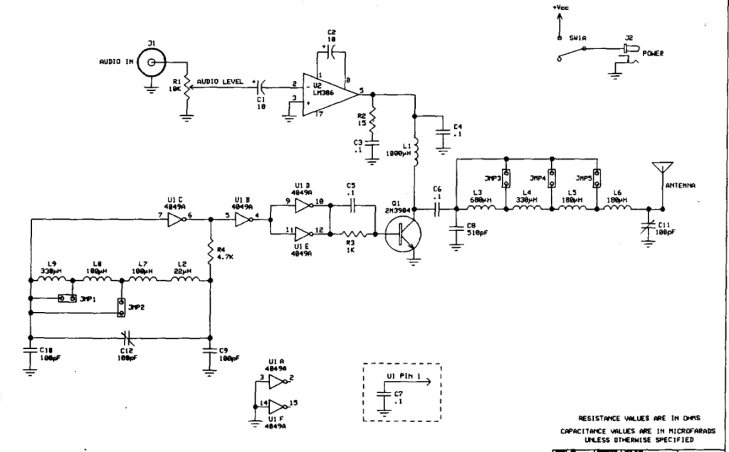
It has a switchable pi-network on its output, which is in fact a 3rd order LPF and matching network in one. Harmonic suppression is not superb, but it is probably satisfying with QRP and a short antenna.
VBR from Ivan
VBR from Ivan
Ivan- Posts : 793
Join date : 2012-11-25
Age : 64
Location : Praha, Czechia
Re: MW Transmitter Idea
![]() by dare4444 Mon Sep 20, 2021 1:00 pm
by dare4444 Mon Sep 20, 2021 1:00 pm
Have u seen the vectronics 1290k schematic?
dare4444- Posts : 427
Join date : 2013-03-19
Re: MW Transmitter Idea
![]() by Ivan Mon Sep 20, 2021 7:24 am
by Ivan Mon Sep 20, 2021 7:24 am
Hi,
it looks like it might work. A (switchable?) LPF on the output would be required to suppress radiation of harmonics - e.g. for 625 kHz the 2nd harmonic is also in the MW band, the 3rd one is in the 160m ham band...
VBR from Ivan
it looks like it might work. A (switchable?) LPF on the output would be required to suppress radiation of harmonics - e.g. for 625 kHz the 2nd harmonic is also in the MW band, the 3rd one is in the 160m ham band...
VBR from Ivan
Ivan- Posts : 793
Join date : 2012-11-25
Age : 64
Location : Praha, Czechia
Re: MW Transmitter Idea
![]() by dare4444 Sun Sep 19, 2021 9:44 pm
by dare4444 Sun Sep 19, 2021 9:44 pm
With 5 crystals and eight DIP switches, we have eight different crystal controlled medium wave band frequencies. CD4069 oscillator driving a CD4040 divider which in turns feeds CD4013 flip flop with 2F signal to produce the required frequencies in 0 and 180 degrees phase shift to drive two 2n7000 or BS170 in pushpull mode and modulated by a LM386. Secondary winding of feritte rod is tuned by a variable capacitor and steps up the voltage to match the high impedance of a 6 foot wire antenna.
Your comments please? No VFO, No PLL but still has 8 different MW frequencies with no drift and easy to build! Four ICs and two mosfets.
Isn't it cool????
Your comments please? No VFO, No PLL but still has 8 different MW frequencies with no drift and easy to build! Four ICs and two mosfets.
Isn't it cool????
dare4444- Posts : 427
Join date : 2013-03-19

» Another low power FM transmitter idea.
» 2n7000 X 3 , Class E Part15 Transmitter Idea
» SDR idea
» PWM AM TX IDEA
» Receiver idea
» 2n7000 X 3 , Class E Part15 Transmitter Idea
» SDR idea
» PWM AM TX IDEA
» Receiver idea
Permissions in this forum:
You can reply to topics in this forum