GDO circuit revisited


Re: GDO circuit revisited
![]() by Ivan Fri Sep 01, 2023 7:47 am
by Ivan Fri Sep 01, 2023 7:47 am
you probably know that KSY transistors are designed for switching purposes primarily. They have high fT to achieve fast transitions between on and off. Nevertheless they may work well in oscillators. KF transistors are linear RF types, KF173/4 were intended for FM tuners (i.e. up to 110 MHz) as mixers, oscillators, ev. IF amplifiers.
Feel free to use a detector from any other design. I personaly consider the quasi-symmetric one with a dual gate FET as weird a bit.
Shielding is often good in RF circuits, but may be excessive if the board is designed cleverly. You will see.
VBR from Ivan
Ivan- Posts : 793
Join date : 2012-11-25
Age : 64
Location : Praha, Czechia
Re: GDO circuit revisited
![]() by MrWifiHifi Thu Aug 31, 2023 6:40 pm
by MrWifiHifi Thu Aug 31, 2023 6:40 pm
MrWifiHifi- Posts : 21
Join date : 2022-06-21
Re: GDO circuit revisited
![]() by Ivan Wed Aug 30, 2023 12:59 pm
by Ivan Wed Aug 30, 2023 12:59 pm
It depends on the sensitivity of the counter
or is an amplifier necessary if I want to have the counter connected even in absorption wavemeter mode?
The counter will never show you the frequency of the tuned circuit in absorption mode. No signal is generated in such case. You can indicate the frequency of a signal "sucked" from outside, but that can be accomplished using a simple untuned coupling loop, too.
if I wanted to know at what frequency it oscillates, I would just turn on the GDO oscillator and thus I would get a frequency at the output how did I tune it in absorption wavemeter mode?
No. By switching the oscillator on the parasitic capacitances change and the GDO tuning changes as well. Frequency scales in absorption mode and oscillation mode are slightly different.
Or is it enough to know the frequency only approximately?
All GDO measurements are rather approximate.
I have some transistor radios from the scrap yard that have input units, I would like to try to tune one with a GDO. I would also like to try to build a simple filter for 2m (144MHz band), because in the dormitory where I go to university, I receive a very good signal from nearby repeater, I often listen to contests or evening chats on the transmitter via USB-SDR. I would like to build my own small receiver for the 2m band for such purposes, as I do not yet have a license for broadcasting and SDR exemption is not just it
You intend to convert a FM superhet to 2m NBFM RX for repeater monitoring, right? There may be a problem with demodulation and with the IF bandwidth: commercial broadcasting is WBFM, while hams use NBFM.
More on the input from SM0VPO, I wanted to know why he designed the GDO the way he did. Why did he choose exchangeable coils with a tap in the middle of the coil, why is oscillator powered trought the tap of a coil, what is the better in circuit of the indicator that he used versus the wiring with the detector, why did he choose a JFET instead of a BJT transistor, and how is the tuned circuit better if it is tuned with 2 tuning capacitors instead of one (and a coil with 3 leads versus 2 leads) .
I expect Harry will answer this.
I am currently still working on building a small coil winder using a stepper motor and an Arduino with a counter for the number of turns and motor speed regulation. When I complete it and put it together, I will add some photos here.
What a nice project! Almost necessary when making power and AF transformers and coils. Most RF coils have few turns only, so they can be easily wound by hand.
VBR from Ivan OK1SIP
Ivan- Posts : 793
Join date : 2012-11-25
Age : 64
Location : Praha, Czechia
Re: GDO circuit revisited
![]() by Ivan Wed Aug 30, 2023 12:25 pm
by Ivan Wed Aug 30, 2023 12:25 pm
I am really pleased by your interest in hamradio. I want to support you.
So far, I wound 10t with 0.5mm wire on the coil that was used in an old Russian TV (diameter 7.5mm), tap in the middle. I measured the coil using the Tesla BM342 GDO that I have, so the coil oscillated somewhere between 30 and 60 MHz, I used the tuning capacitor from some radio, it has an AM and FM part, I have no idea what are the min/max capacities there + are there also fine-tuning capacity trimmers .
The AM antenna section of a tuning capacitor usually changes between cca 30 pF and 300 pF (maybe 25 - 250 pF or 35 - 350 pF). The oscillator section may be the same or slightly smaller. The two FM sections are nearly 10 times smaller than the AM ones. The trimmers are added for achieving of three point tracking in a superhet and are of no interest to you.
What I am also interested in is how the resonant frequency is calculated for a tuned circuit that is tuned by 2 capacitors (picture no. 1 and no. 2). I haven't worked out a reasonable calculation yet, everything is just for a parallel LC resonant circuit.
Simply evaluate the serial/parralel combination of all capacitors and apply the result in the famous Thompson formula (valid both for serial and parralel LC circuit).
I also wanted to ask if anyone could recommend some literature intended for radio amateurs focused on the construction of coils, I still do not understand very well what the taps are for and why capacitors are connected to them in some connections.
Consider a tapped coil as an autotransformer. The voltage on the tap is reduced according to the ratio of number of turns of the tap vs. the whole coil, the current is increased according the same ratio, the impedance is transformed according to the square of that ratio. Taps are often used to match the impedance of a resonant circuit to the impedance of the transistor.
A GDO really can replace a RF generator to some extent. I have never used headphones with a GDO.
See next part.
Ivan- Posts : 793
Join date : 2012-11-25
Age : 64
Location : Praha, Czechia
Re: GDO circuit revisited
![]() by MrWifiHifi Tue Aug 29, 2023 11:41 pm
by MrWifiHifi Tue Aug 29, 2023 11:41 pm
Since the last time I spoke, I have made some progress, I am attaching a picture with the schematics I had in mind. After a little tinkering with the circuits, I've come up with this so far:
First of all, I have to rule out the Collpits oscillator circuit for now, as apparently the capacitance divider connected between the base emitter and ground should be changed for each band.
In the second row, I tried to change the GDO circuit according to SM0VPO, as I solved it here earlier in the thread, by replacing the JFET transistor with an NPN BJT, unfortunately it didn't want to oscillate, some modification in the circuit will be needed.
Furthermore, in addition to the circuit of the GDO Heathkit HD-1250 (picture no. 1), I worked on the circuit of the GDO KENWOOD DM-81 (picture no. 2) on the internet, which I quite liked. Oscillator with NPN transistor, replaceable coils with only 2 outputs, RF output option on the connector, 1KHz signal modulation option, battery powered and according to the documentation only 9mA consumption.
So far, I wound 10t with 0.5mm wire on the coil that was used in an old Russian TV (diameter 7.5mm), tap in the middle. I measured the coil using the Tesla BM342 GDO that I have, so the coil oscillated somewhere between 30 and 60 MHz, I used the tuning capacitor from some radio, it has an AM and FM part, I have no idea what are the min/max capacities there + are there also fine-tuning capacity trimmers .
What I am also interested in is how the resonant frequency is calculated for a tuned circuit that is tuned by 2 capacitors (picture no. 1 and no. 2). I haven't worked out a reasonable calculation yet, everything is just for a parallel LC resonant circuit.
I also wanted to ask if anyone could recommend some literature intended for radio amateurs focused on the construction of coils, I still do not understand very well what the taps are for and why capacitors are connected to them in some connections.
What else I noticed about the KENWOOD GDO is that the oscillator can be modulated at 1kHz, and there is also an output for a 3.5mm jack headphone. If understood correctly, not only can the received signal be monitored in the absorption wavemeter mode, but if the oscillator were modulated by 1kHz, then we should hear a demodulated 1kHz signal at the output and thus it can also serve as an acoustic indication of dips . Is that so?
I would perhaps add some kind of buffer circuit to the KENWOOD connection, so that the oscillator could be connected to the counter and at the same time take the signal from it for measurement in the circuit (see manual for KENWOOD DM-81).
If I managed to put together something similar to the KENWOOD one, it would be a very useful device, then I wouldn't need to build an RF generator for testing RF circuits and tuning radios.
As for connecting the GDO to the counter, is it necessary to somehow buffer the signal, or is an amplifier necessary if I want to have the counter connected even in absorption wavemeter mode? Alternatively, it could also be solved by measuring the circuit in absorption wavemeter mode for the largest deviation, if I wanted to know at what frequency it oscillates, I would just turn on the GDO oscillator and thus I would get a frequency at the output how did I tune it in absorption wavemeter mode? Or is it enough to know the frequency only approximately?
I have some transistor radios from the scrap yard that have input units, I would like to try to tune one with a GDO. I would also like to try to build a simple filter for 2m (144MHz band), because in the dormitory where I go to university, I receive a very good signal from nearby repeater, I often listen to contests or evening chats on the transmitter via USB-SDR. I would like to build my own small receiver for the 2m band for such purposes, as I do not yet have a license for broadcasting and SDR exemption is not just it
More on the input from SM0VPO, I wanted to know why he designed the GDO the way he did. Why did he choose exchangeable coils with a tap in the middle of the coil, why is oscillator powered trought the tap of a coil, what is the better in circuit of the indicator that he used versus the wiring with the detector, why did he choose a JFET instead of a BJT transistor, and how is the tuned circuit better if it is tuned with 2 tuning capacitors instead of one (and a coil with 3 leads versus 2 leads) .
I am currently still working on building a small coil winder using a stepper motor and an Arduino with a counter for the number of turns and motor speed regulation. When I complete it and put it together, I will add some photos here.
Thanks in advance for the answer and sorry for so many questions, but I'm very interested


MrWifiHifi- Posts : 21
Join date : 2022-06-21
Re: GDO circuit revisited
![]() by Ivan Fri Aug 25, 2023 9:46 am
by Ivan Fri Aug 25, 2023 9:46 am
Hello,MrWifiHifi wrote:Hello
I will try to process it e.g. in pdf form and then I'll send it here, I'm having a hard time working with pictures here
that is strange. There should be no problem to host a JPEG image on servimg and link it with this conference.
VBR from Ivan
Ivan- Posts : 793
Join date : 2012-11-25
Age : 64
Location : Praha, Czechia
Re: GDO circuit revisited
![]() by MrWifiHifi Thu Aug 24, 2023 4:09 pm
by MrWifiHifi Thu Aug 24, 2023 4:09 pm
I will try to process it e.g. in pdf form and then I'll send it here, I'm having a hard time working with pictures here
MrWifiHifi- Posts : 21
Join date : 2022-06-21
Re: GDO circuit revisited
![]() by Ivan Tue Aug 15, 2023 5:20 pm
by Ivan Tue Aug 15, 2023 5:20 pm
"One of the two detector connections would be used..." I can see one detector only??
Two or three varicaps in parralel instead of one (i.e. 4 resp. 6 pcs total) may be needed to achieve a reasonable tuning range at HF bands.
VBR from Ivan
Ivan- Posts : 793
Join date : 2012-11-25
Age : 64
Location : Praha, Czechia


MrWifiHifi- Posts : 21
Join date : 2022-06-21
Re: GDO circuit revisited
![]() by MrWifiHifi Tue Aug 15, 2023 10:08 am
by MrWifiHifi Tue Aug 15, 2023 10:08 am
I didn't hear from you for a long time. I thought of a few more things regarding GDO, but its involvement would probably be more complicated compared to sm0vpo GDO.
In the magazine "Amateur radio" I found these 2 connections that inspired me. Both connections use varicaps for tuning. both use a negative supply voltage. Both circuits use a Colpitts oscillator, a tuned LC circuit is connected to the collector of the transistor.
I thought of putting the LC circuit separately (see picture), I saw such an oscillator connection in some HAM literature. Thus, if the LC circuit were connected in this way, it could be immediately used for an absorption wavemeter. One of the two detector connections would be used for the indicator, the output would go to a 100uA needle meter.
The circuit would be powered by a 9V battery, the oscillator would be powered by 5V from a zener diode, and the tuning voltage would be taken from 9V. Alternatively, perhaps the GDO could be supplemented with a voltage converter for 33V from which the tuning voltage would be taken (it should be possible to achieve greater tuning.
It would still be possible to somehow complete the output for the counter for digital display of the frequency.
Apart from the coil connector, the scope coils themselves, the switches and the dial gauge, all the parts for the GDO should be available from old channel tuner.
By using varicaps in circuit, it would be possible to superimpose an audio signal on the tuning voltage and thus modulate the RF.
Some things could be added to this GDO, but I would probably leave it up to everyone to add what suits them there.


MrWifiHifi- Posts : 21
Join date : 2022-06-21
Re: GDO circuit revisited
![]() by Ivan Wed Jul 13, 2022 7:30 am
by Ivan Wed Jul 13, 2022 7:30 am
Hi,MrWifiHifi wrote:From left, there is the oscilator, S1 turns oscilator on and off, I didn't include uA meter. The X in oscillator schematic indicates, where I want to put switch to disconnect second LC circuit when using GDO as wavemeter.
the S1 should be a DPST switch, one pole disconnecting the battery, the other one opening the feedback LC circuit. It seems to work.
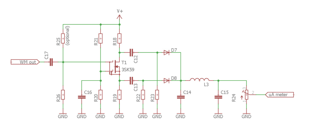
The dual gate MOSFET works as a cascode amplifier (common source - common gate, two stages in one device) here. The input shall be G1, while G2 is RF grounded. You drew a wrong assignment of gates!Next there is heatkitnstyle dual gate mosfet rectifier.
Surely via a capacitor. You do not want the DC voltage from the oscillator to change the bias of the cascode. G1 is often self-biased, maybe a resistor to GND shall be used. G2 is biased from a voltage divider and RF grounded. Confront some more schematics, I lack personal experience with design of DG MOSFET amplifiers.Should it be connected trough capacitor or could it be connected directly? If it needs to be connected trough the cap, does the g2 need extra resistor to adjust its bias point
Schottky or common silicon low power diodes will do. A 3rd order low pass filter is rather an overkill, one capacitor in the order of nanofarads should do. If you want, use any choke blocking RF in place of L1. A variable resistor can be added to change the sensitivity.What type of diodes should be used and what value L1 should be? Is there any way to add sense control to this rectifier circuit?
VBR from Ivan
Ivan- Posts : 793
Join date : 2012-11-25
Age : 64
Location : Praha, Czechia
sm0vpo likes this post
Re: GDO circuit revisited
![]() by MrWifiHifi Tue Jul 12, 2022 10:51 am
by MrWifiHifi Tue Jul 12, 2022 10:51 am
From left, there is the oscilator, S1 turns oscilator on and off, I didn't include uA meter. The X in oscillator schematic indicates, where I want to put switch to disconnect second LC circuit when using GDO as wavemeter. Next there is heatkitnstyle dual gate mosfet rectifier. I don't know, hot to connected to the original GDO circuit. Should it be connected trough capacitor or could it be connected directly? If it needs to be connected trough the cap, does the g2 need extra resistor to adjust its bias point (what would be values of R1 and R2)? Is point for connecting rectifier chosed right? What type of diodes should be used and what value L1 should be? Is there any way to add sense control to this rectifier circuit?

MrWifiHifi- Posts : 21
Join date : 2022-06-21
Re: GDO circuit revisited
![]() by Ivan Mon Jul 04, 2022 8:20 am
by Ivan Mon Jul 04, 2022 8:20 am
Common switches should suffice up to 100 MHz or more. Try to get types with low capacity between open contacts.MrWifiHifi wrote:About switches on LC circuit, I was concered that they need to be some special switches for RF or they must be connected in some special way. Is it enough, if I use regular switches and just keep connections between them and LC as short as possible?
There are two parralel LC circuits in the original schematic by SM0VPO, cited at the beginning of this thread. C2 is a short for RF. One circuit is connected to the drain of the JFET, the other to its gate. Both circuits are coupled by mutual inductance.I meant, that in the original schematic, there are two series tuned LC circuits. I was just thinking, if it would be better, if for wavemeter there would be LC connected as parallel not series. But that was just thought.
I would prefer the PCB sheet. A metal box may be hard to solder on (big thermal conductivity, destroying the paint by heat) and have other disadvanteges:What is better for ground? Unetched PCB or if I use metal box for GDO and use it as a ground?
copper - heavy, expensive;
aluminum and its alloys - cannot be soldered by a SnPb alloy easily;
iron - worse conductivity. But thin tin plated iron is good for shielding boxes.
Many homebrewers make boxes from unetched PCB material, the copper foil inwards, soldered on all edges. These make a good ground and shielding, too.
Ready made planet gear is easy to use. But the selection is upon you.About that transmission for tuning cap, I have some older russian radio that is using string transmission with just two wheels (tuning knob and capacitor wheel). I don't want to use gears, because with the transmission system I have in mind, anybody can easily modify transmission factor, but I wolud want to use gears, that would be more difficult.
If you used a logarithmic amplifier (e.g. LT5537), maybe the sensitivity control would become unnecessary. Think of it.But for now, I don't know how to add the sensitivity control for that kind of circuit.
Do so, please!(If I have some free time, I'll add the schematic of it)
VBR from Ivan
Ivan- Posts : 793
Join date : 2012-11-25
Age : 64
Location : Praha, Czechia
sm0vpo likes this post
Re: GDO circuit revisited
![]() by MrWifiHifi Sun Jul 03, 2022 9:59 pm
by MrWifiHifi Sun Jul 03, 2022 9:59 pm
I meant, that in the original schematic, there are two series tuned LC circuits. I was just thinking, if it would be better, if for wavemeter there would be LC connected as parallel not series. But that was just thought.
Your description of measuring unknown ferrite rod is straight forward and easy to understand. Thank you for that, I like it very much
What is better for ground? Unetched PCB or if I use metal box for GDO and use it as a ground?
I want to make my own box for GDO from sheet metal, so I am thinking of apptoximate dimensions of it. I am still thinking if it would be better to build everything to one box or for example if counter should be external.
About that transmission for tuning cap, I have some older russian radio that is using string transmission with just two wheels (tuning knob and capacitor wheel). I don't want to use gears, because with the transmission system I have in mind, anybody can easily modify transmission factor, but I wolud want to use gears, that would be more difficult.
So, I was sketching to my notebook some circuit design for GDO and I came up with some thing. I would disconnect meter how is it connected in original schematic. I would connect somehow heatkit detector to the drain of BF245, so it can also measure the dips of oscilator. But, here comes the best part. If some switches be added to circuit, the JFET could be disconnected, detector would be connected to LC circuit so it could function as wavemeter too. But for now, I don't know how to add the sensitivity control for that kind of circuit.
What do you think about it? (If I have some free time, I'll add the schematich of it)
MrWifiHifi- Posts : 21
Join date : 2022-06-21
Re: GDO circuit revisited
![]() by Ivan Fri Jul 01, 2022 9:27 pm
by Ivan Fri Jul 01, 2022 9:27 pm
Opening or shorting the unnecessary LC circuit by a contact will do. What is the problem?MrWifiHifi wrote:Regarding the wavemeter, I wanted to ask how it would be possible to make the mechanical part of the switches for the LC circuit? Only one winding out of the two available will be needed for the wavemeter, so one part will have to be disconnected,
I see a dual parralel resonant circuit in the original schematic. Which schematic do you have in mind?it would also probably be better if the circuit was switched to a parallel LC instead of a serial one, but I have yet to try that.
It can be done easily. Wind one (n=1) or e.g. ten turns of wire on the core and measure their inductance Lo. The AL of the core is equal to Lo in the first case, resp. AL = Lo/100 in the second case. An inductor wound on that core than has inductance L = AL*n^2 To establish the frequency range, test the Q on a set of frequecies.I have some ferrites from old radios, but I don't know what their properties are. Is it a big deal? Alternatively, the properties of the given ferrite cannot be determined somehow...?
"Regarding the GDO mechanics, I have a few questions. How should the individual components be connected, what must be strictly followed during build?"
Keep part connections as short as possible. Use a wide, low-impedance ground - e.g. a piece of unetched PCB material. Use shielding if necessary to avoid unwanted feedback and/or spurii from the digital counter.
"How would it be best to squeeze the GDO scale (rotary scale on tuning capacitor) and counter into one box?"
What is the problem? Much depends on the box you want to use.
"Would it be a good idea to add a transmission to the tuning capacitor, e.g. 2:1 or 3:1 for finer tuning?"
Probably YES. I have an old Soviet GDO with 1:10 planet gearbox. This one may be of interest for you.
"I also wondered if the needle meter could be used for both the GDO and the wavemeter and even for checking the battery level."
YES, it is a matter of switching only.
VBR from Ivan
Ivan- Posts : 793
Join date : 2012-11-25
Age : 64
Location : Praha, Czechia
Re: GDO circuit revisited
![]() by MrWifiHifi Fri Jul 01, 2022 12:13 pm
by MrWifiHifi Fri Jul 01, 2022 12:13 pm
Regarding the wavemeter, I wanted to ask how it would be possible to make the mechanical part of the switches for the LC circuit? Only one winding out of the two available will be needed for the wavemeter, so one part will have to be disconnected, it would also probably be better if the circuit was switched to a parallel LC instead of a serial one, but I have yet to try that.
I have some ferrites from old radios, but I don't know what their properties are. Is it a big deal? Alternatively, the properties of the given ferrite cannot be determined somehow...?
I would like to use the GDO in the attached photos in the previous post only as inspiration for the mechanical design of the GDO.
Regarding the GDO mechanics, I have a few questions. How should the individual components be connected, what must be strictly followed during build?
How would it be best to squeeze the GDO scale (rotary scale on tuning capacitor) and counter into one box?
Would it be a good idea to add a transmission to the tuning capacitor, e.g. 2:1 or 3:1 for finer tuning?
I also wondered if the needle meter could be used for both the GDO and the wavemeter and even for checking the battery level.
MrWifiHifi- Posts : 21
Join date : 2022-06-21
Re: GDO circuit revisited
![]() by Ivan Tue Jun 28, 2022 2:39 pm
by Ivan Tue Jun 28, 2022 2:39 pm
Hi,MrWifiHifi wrote:I wanted to ask more about the counter, I was thinking about AT89C2051 with some prescaler, SAB6456 for example (probably the only one that can be bought where I live). I would like to use 6 LED displays, ideal if the counter should switch ranges for kHz and MHz.
sorry, I have no personal experience about that.
Obviously you mean a wavemeter, not waveguide.As for the absorption waveguide, I'm still thinking about how to design the circuit. I'll probably build the whole GDO first and I'll slowly build the wavemeter inside the box.
YES, it is possible. NO, I do not expect any problem. Just select the proper ferrite mix for the frequency band. Most ferrite rods are intended for AM antennae and they are made of mix best for 1-5 MHz (Pramet N1, Amidon 61). You may want some other mix (e.g. Pramet H12). You may also use small toroid or pot cores, glue them together to make a rod and wind the coil on its surface, not passing through the center.MrWifiHifi wrote:I would also like to know if it would be possible to use ferrite rods and thus reduce the number of windings at the lowest ranges. Would there be a problem with that?
Toroidal winding would be no good in this case, of course.
Surely, YES.Would it be possible to calibrate the scale using a USB RTL-SDR receiver?
Well, the GDO on the photo IMHO cannot be switched to the wavemeter mode.I attached a photo of GDO, which I found on the Internet, and according to which I would like to be inspired during the construction.
VBR from Ivan
Ivan- Posts : 793
Join date : 2012-11-25
Age : 64
Location : Praha, Czechia

MrWifiHifi- Posts : 21
Join date : 2022-06-21


MrWifiHifi- Posts : 21
Join date : 2022-06-21
Re: GDO circuit revisited
![]() by MrWifiHifi Tue Jun 28, 2022 11:17 am
by MrWifiHifi Tue Jun 28, 2022 11:17 am
As for the absorption waveguide, I'm still thinking about how to design the circuit. I'll probably build the whole GDO first and I'll slowly build the wavemeter inside the box.
I wanted to ask how to calculate the coils for the GDO approximately? I know that in the second version the coils are only for bands from 1.7MHz which will probably not be enough. It would also like ranges for the kHz band. I would also like to know if it would be possible to use ferrite rods and thus reduce the number of windings at the lowest ranges. Would there be a problem with that?
Would it be possible to calibrate the scale using a USB RTL-SDR receiver?
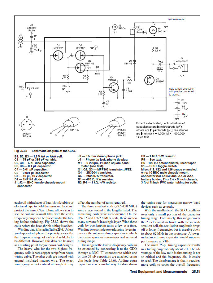
I attached a photo of GDO, which I found on the Internet, and according to which I would like to be inspired during the construction. I also attach a page from the ARRL manual where the construction of the GDO is also described.

MrWifiHifi- Posts : 21
Join date : 2022-06-21
Re: GDO circuit revisited
![]() by Ivan Thu Jun 23, 2022 6:43 pm
by Ivan Thu Jun 23, 2022 6:43 pm
Radšej sa držme angličtiny, aby aj ostatný hamovia mali dačo z našej diskuzie.MrWifiHifi wrote:I'm glad to hear that, I'm sorry I didn't notice it before. Môžme teda písať aj po našom
(ukázka bývalé "armádní českoslovenštiny" - na vojně jsem byl ve Zvolenu
Let us stay with the English language, so that other hams cam make use of our discussion.
IMHO it is worth trying. It should work.MrWifiHifi wrote:How, then, would it be possible to wire up a wavemeter as I described it?
VBR from Ivan OK1SIP
Ivan- Posts : 793
Join date : 2012-11-25
Age : 64
Location : Praha, Czechia
sm0vpo likes this post
Re: GDO circuit revisited
![]() by MrWifiHifi Thu Jun 23, 2022 11:56 am
by MrWifiHifi Thu Jun 23, 2022 11:56 am
I'm glad to hear that, I'm sorry I didn't notice it before. Môžme teda písať aj po našomIvan wrote:Slovakia? So we are neighbours!
So I specifically found that involvement in the book "Měření a slaďovaní amatérskych přijímaču".Ivan wrote:Hello,
you probably know, that a positive feedback makes a circuit to oscillate. The feedback may be done via:
- a separate winding, which would require 4 pins to change the coil;
- an autotransformer = a taped coil, which needs 3 pins;
- a capacitive divider, a coil can have two pins only (typically the Colpitts oscillator). The values of the capacitors of the divider may be critical if the oscillator shall have a wide frequency range. A dual gang variable capacitor (resp. a pair of varicaps) seems to be a must.
How, then, would it be possible to wire up a wavemeter as I described it?
MrWifiHifi- Posts : 21
Join date : 2022-06-21
Re: GDO circuit revisited
![]() by Ivan Thu Jun 23, 2022 6:38 am
by Ivan Thu Jun 23, 2022 6:38 am
Hello,MrWifiHifi wrote:I read in older book, that 3 pin coil in oscillator circuit for low frequencies, because it won't oscillate right.
you probably know, that a positive feedback makes a circuit to oscillate. The feedback may be done via:
- a separate winding, which would require 4 pins to change the coil;
- an autotransformer = a taped coil, which needs 3 pins;
- a capacitive divider, a coil can have two pins only (typically the Colpitts oscillator). The values of the capacitors of the divider may be critical if the oscillator shall have a wide frequency range. A dual gang variable capacitor (resp. a pair of varicaps) seems to be a must.
Slovakia? So we are neighbours!
VBR from Ivan
Ivan- Posts : 793
Join date : 2012-11-25
Age : 64
Location : Praha, Czechia
Re: GDO circuit revisited
![]() by MrWifiHifi Wed Jun 22, 2022 8:50 pm
by MrWifiHifi Wed Jun 22, 2022 8:50 pm
For now, I can use just tuning capacitor. Maybe same day in the future I would want to design it with varicaps.
I think it would be very practical and useful, to have 2 devices in one package. I'm just working with older literature and internet, so there is plenty of inspiration.
Yes, the KF910 was made by Tesla in former Czechoslovakia, I'm from Slovakia
MrWifiHifi- Posts : 21
Join date : 2022-06-21
Re: GDO circuit revisited
![]() by Ivan Wed Jun 22, 2022 7:10 pm
by Ivan Wed Jun 22, 2022 7:10 pm
if the GDO is based on a Colpitts oscillator, the measuring coil can have two pins only.
You may want to look here. The schematics can be displayed via the links under the photos. The oscillator uses inductors without a tap. The project replaces the variable capacitor, mechanical dial and microammeter with varicaps and a MCU. It seems not to work as a wavemeter, though.
I like the idea of building a wavemeter as a circuit separate from the GDO, but with common LC resonator.
KF910? It looks like Tesla, Czechoslovakia make.
VBR from Ivan OK1SIP
Ivan- Posts : 793
Join date : 2012-11-25
Age : 64
Location : Praha, Czechia
Re: GDO circuit revisited
![]() by MrWifiHifi Wed Jun 22, 2022 12:39 pm
by MrWifiHifi Wed Jun 22, 2022 12:39 pm
However, both circuits have something in common, the LC circuit conections. It is quite similar to what is in your GDO design. I added a picture as I redrawn this circuit. I figured out that in your GDO were actually 2 series-tuned circuits. In the GDO from Heatkit, the connection of the coil was similar (it did not have 3 but only 2 pins) but the detector for the wavemeter was connected directly to the coil. The picture shows how the coils were connected and then the detector schamtic. In the original connection, it uses a double gate mosfet (I only have KF910 in my stock, it's a domestic version, probably BF910), it has full wave rectifier, a filter and a meter behind it. It might be possible to connect an LC circuit to the detector, but a decoupling capacitor would be needed there. If it were connected in this way, it would probably be necessary to bias the gate mosfet, as it is not in the original connection.
Personally, I think that with similar modifications, something similar could be added to your GDO, I quite like the connection of the Heatkit detector, if I wanted to build something similar, I would probably go to single gate/base J-FET or bipolar transistor.
What is your opinion on this?

MrWifiHifi- Posts : 21
Join date : 2022-06-21
sm0vpo likes this post
Re: GDO circuit revisited
![]() by sm0vpo Wed Jun 22, 2022 8:35 am
by sm0vpo Wed Jun 22, 2022 8:35 am
The GDO was not designed to be used as a wave-meter, but it does work as a passive wave-meter if you use a bipolar transistor.
If you want a sensitive or active wave-meter then you could make another unit in a similar box and using the same coils. You could alternatively build the two units in the same box and have a switch for GDO/W-M to connect the tuned circuit to either circuit. This could affect performance on the higher frequency bands, above 150MHz.. But this is outside the scope of this GDO project.
The meter movement in the GDO is a 100μA unit and you could use something like zero-bias Schottky diode to detect the RF at the base/gate of the transistor and use the DC to feed the meter using a second contact on the power ON/OFF switch: that is to say diode detector in circuit when the GDO is switched off. Standard detector/switching diodes need 100mV to 700mV before they conduct.
As regards the counter output, you could use a high-impedance tapping from the base/gate of the device to feed a counter, but this could also affect the VHF calibration.
I suggest that you have a good think about your requirements and see if you can come up with something that works. It all depends on how far you want to go and how much time you want to spend on it. If you do add more functions to the GDO then please post it here and give us all the benefit of your experience.
Very best regards from Harry - sm0vpo
(PS - I just love it when thinking people like you can take an idea and throw it around for further development. Very often it can lead to great improvements in an existing project
sm0vpo- Admin
- Posts : 110
Join date : 2013-03-26
Age : 72
Location : Märsta, Sweden
Re: GDO circuit revisited
![]() by MrWifiHifi Wed Jun 22, 2022 8:07 am
by MrWifiHifi Wed Jun 22, 2022 8:07 am
I still wanted to ask how to buffer the signal for the counter? If the GDO is in wavemeter mode, will the signal need to be amplified and separated for the counter, if the counter is not sensitive enough?
MrWifiHifi- Posts : 21
Join date : 2022-06-21
Re: GDO circuit revisited
![]() by Ivan Wed Jun 22, 2022 6:32 am
by Ivan Wed Jun 22, 2022 6:32 am
Hi,MrWifiHifi wrote:I'd like to ask about that absorption wavemeter. If I understood correctly (from older circuit designs i found), then the wavemeter consists of a tuned LC circuit, behind which is an amplifier and a detector, it actually measures the voltage on the LC circuit. How would it be possible to adjust your circuit design for this type of wavemeter? I assume that it will be necessary to change the LC connection to the circuit, then add an amplifier and a detector. I am thinking that a counter can also be connected to the wavemeter and thus that the tuned frequency can be displayed. Well, if it's possible in any other way, I'll be happy to advise you.
the basic wavemeter is a passive device: a tuned LC circuit, a diode detector, a sensitivity potentiometer and a microammeter. No power source is required. A switched off GDO with a bipolar transistor works in that manner, too: the junction inside the transistor works as a detection diode. The scale for a GDO and an absorption wavemeter may differ slightly due to different internal capacity of the transistor as an oscillator vs. as a detector.
A counter cannot display the "tuned frequency", but the frequency of the inbound signal (independent of the variable capacitor setting), provided that the counter is sensitive enough.
Wavemeters for UHF and microwave range employ some form of tuned stub or hollow resonator instead of a tuned circuit.
VBR from Ivan OK1SIP
Ivan- Posts : 793
Join date : 2012-11-25
Age : 64
Location : Praha, Czechia
Re: GDO circuit revisited
![]() by MrWifiHifi Tue Jun 21, 2022 8:36 pm
by MrWifiHifi Tue Jun 21, 2022 8:36 pm
I'd like to ask about that absorption wavemeter. If I understood correctly (from older circuit designs i found), then the wavemeter consists of a tuned LC circuit, behind which is an amplifier and a detector, it actually measures the voltage on the LC circuit. How would it be possible to adjust your circuit design for this type of wavemeter? I assume that it will be necessary to change the LC connection to the circuit, then add an amplifier and a detector. I am thinking that a counter can also be connected to the wavemeter and thus that the tuned frequency can be displayed. Well, if it's possible in any other way, I'll be happy to advise you.
MrWifiHifi- Posts : 21
Join date : 2022-06-21
Re: GDO circuit revisited
![]() by sm0vpo Tue Jun 21, 2022 1:12 pm
by sm0vpo Tue Jun 21, 2022 1:12 pm
The GDO I originally built around 1980 was a joint project with some of the technicians I had in my workshop. I gave them the circuit, and because it uses a Wheatstone's bridge it gives greater sensitivity. Many of the technicians made all manner of boxes. One of them even had a coil with a scale, so that when you plugged in a coil it also pushed the relevant scale under the dial.
I was working in Saudi for the National Guard, where there were 14 repeater sites in each major city. The received audio at site was fed back to a control center, where the best signal was then selected and sent to FM transmitters at all 14 sites. Different areas had different frequencies. The audio levels were quite critical. They also had a 71.9Hz sub-audio tone to open the squelch of the receivers.
Our GDOs had an in-built modulation system that generated 71.9Hz and 1KHz. The 71.9 modulated to 12% of the system deviation and the 1kHz modulated to 60%. This means that the GDO could be tuned to 10.7MHz, open the receiver squelch and inject a test audio signal at -4.5dBmO.
It didn't matter what frequency the receivers were, the RF was picked up by the 10.7MHz IF amplifier.
If you look at the old 40 year old project you will see that there is a switch, this it to switch the modulation ON and OFF. The two audio tones were fed into the emitter/source of the transistor through a 100k (if I remember rightly) potentiometer, and the pot was adjusted to give the correct FM deviation. Plug in the 100Mhz coil and the deviation increases to about +/-50kHz. This you can adjust by the pot.
It is really easy to implement. The GDO can also supply about +10dBm with a coupling loop wound on the coil. I have also used the GDO to drive a 40dB gain amplifier and got almost 10 Watts out of it.
One point is that the frequency can drift a little bit as the transistors warms microscopically, usually in the first 60 seconds. At 10.7MHz it is rock-stable.
So, to modulate with FM you only need to stuff a signal into the emitter/source terminal of the oscillator device. No varactor/varicap diodes or anything.
One small point is that this system of modulation will give BOTH AM and FM together on the same carrier. I am not sure how deep the AM depth is.
Have I answered your question?
BR Harry - sm0vpo
sm0vpo- Admin
- Posts : 110
Join date : 2013-03-26
Age : 72
Location : Märsta, Sweden
Re: GDO circuit revisited
![]() by MrWifiHifi Tue Jun 21, 2022 11:57 am
by MrWifiHifi Tue Jun 21, 2022 11:57 am
Sorry for so many question, but I'm too curious
MrWifiHifi- Posts : 21
Join date : 2022-06-21
sm0vpo likes this post
Re: GDO circuit revisited
![]() by sm0vpo Tue Jun 21, 2022 11:29 am
by sm0vpo Tue Jun 21, 2022 11:29 am
MrWifiHifi wrote:Ok, so what about varactor diodes as replacement of tuning caps? Could it be used? Would GDO and absorption meter work with them?
Varactor diodes need to have a high capacitance and the large signal level would cause the waveform to distort due to change in capacitance as the voltage follows the waveform. The circuit was designed for a variable capacitor of 275pf + 275pf, dual-gang variable capacitor.
Varactor dioes also require a DC voltage, which means that they will not work if the power is switched OFF, so the unit will not function as an absorption wave-meter with varactor diodes.
So sorry to be a bit negative on this issue, but these are all good question
Best regards Harry - sm0vpo
sm0vpo- Admin
- Posts : 110
Join date : 2013-03-26
Age : 72
Location : Märsta, Sweden
Re: GDO circuit revisited
![]() by MrWifiHifi Tue Jun 21, 2022 10:47 am
by MrWifiHifi Tue Jun 21, 2022 10:47 am
MrWifiHifi- Posts : 21
Join date : 2022-06-21
sm0vpo likes this post
Re: GDO circuit revisited
![]() by sm0vpo Tue Jun 21, 2022 10:05 am
by sm0vpo Tue Jun 21, 2022 10:05 am
MrWifiHifi12345 wrote:Hi
I have BFR90 or BFR91 in my stock, could i use this instead? How it would function as absortion wavemater, is any extra circuity needed or it just need to be turned off to work? Would it be possible to measure frequency...? And what about varicaps?
Yes, those transistors will work fine.
As an absorption wave-meter the bipolar device will simply act as a diode detector (with the GDO switched off), and some of the DC will find it's way to the meter.
the only thing you have to do to get a bipolar to work is to change the 100K resistor to a lower value, such as 10K, and add a 47K resistor from the battery supply to the gate (base) of the transistor. The transistor should draw about 1mA to 2mA.
Very best regards from Harry - sm0vpo
sm0vpo- Admin
- Posts : 110
Join date : 2013-03-26
Age : 72
Location : Märsta, Sweden
Re: GDO circuit revisited
![]() by sm0vpo Tue Jun 21, 2022 10:01 am
by sm0vpo Tue Jun 21, 2022 10:01 am
I have activated both your accounts:
MrWiFiHiFi
MrWiFiHiFi123
You may like to delete one of them. I see that you re logged in as a guest MrWiFiHiFi12345.
You now all the access that a registered member has. You can post pictures, links and edit your own messages, plus loads of other interesting and wonderful things.
Feel free to post any questions and also give us the benefit of your own experiences. remember that there are no stupid questions (including "[i]How many volts do I need to kill someone[/i]?"). I had that question a few years ago. The guy wanted to know what is considered to be a lethal voltage.
I hope that you enjoy the forum and that we can all learn from each other.
Very best regards from Harry Lythall - sm0vpo (admin)
sm0vpo- Admin
- Posts : 110
Join date : 2013-03-26
Age : 72
Location : Märsta, Sweden
Re:GDO circuit revisited
![]() by MrWifiHifi12345 Tue Jun 21, 2022 9:29 am
by MrWifiHifi12345 Tue Jun 21, 2022 9:29 am
I have BFR90 or BFR91 in my stock, could i use this instead? How it would function as absortion wavemater, is any extra circuity needed or it just need to be turned off to work? Would it be possible to measure frequency...? And what about varicaps?
MrWifiHifi12345- Guest
Re: GDO circuit revisited
![]() by sm0vpo Tue Jun 21, 2022 9:14 am
by sm0vpo Tue Jun 21, 2022 9:14 am
So glad that you are interested in this. If you re-work this circuit to use a bipolar transistor, such as the BF199 2N2369, etc, then yet it will also work as an absorption wave-meter, but it does not work using the FET version. Or to but it more accurately, it shouldn't work, but I have not tried it.
If you want to use a 2-terminal coil then use an extra 1K2 resistor from the collector of the transistor, instead of connecting the pot to the center of the coil. It is as easy as that. I used this technique with the MK1 for the UHF coils. The coil sockets were all 3-pin, but with a 1K2 from the "hot" end to the centre-pin.
Have I answered your question?
BR Harry -
sm0vpo- Admin
- Posts : 110
Join date : 2013-03-26
Age : 72
Location : Märsta, Sweden
GDO circuit revisited
![]() by MrWifiHifi Tue Jun 21, 2022 8:53 am
by MrWifiHifi Tue Jun 21, 2022 8:53 am
I would like to build my GDO into a metal box, the frequency would be displayed on LCD or LED display, the tuning and sensitivity would be set by two potentiometers, I would use BNC connectors for the coils, because I have them in stock. I would like to power it with a 9V battery, if varicaps could be used, there would still be some converter for the tuning voltage. Also, if possible, I would like to supplement the GDO with AM and FM modulation using an internal 1KHz oscillator.
Thank you in advance for answer.
MrWifiHifi- Guest
» RF remote control circuit
» Going to give the "lil" "Cigar box receiver" in Harry's site a whirl.
» agc circuit
» tuned circuit
|
|
|