Traffic receiver
2 posters


Re: Traffic receiver
![]() by Ivan Sat Jul 30, 2022 4:07 pm
by Ivan Sat Jul 30, 2022 4:07 pm
I am not 100% sure, but I think it does not. You may send the PDF to Harry, the owner of this forum, via e-mail and he can make it accessible on HHH pages.LA1DEA wrote:Trying to upload the full documentation of the receiver, but ther is a problem.
The forum dont accept PDF upload????
73 LA1DEA
73 Ivan OK1SIP
Ivan- Posts : 794
Join date : 2012-11-25
Age : 64
Location : Praha, Czechia
LA1DEA likes this post
Traffic receiver
![]() by LA1DEA Sat Jul 30, 2022 1:06 pm
by LA1DEA Sat Jul 30, 2022 1:06 pm
Trying to upload the full documentation of the receiver, but ther is a problem.
The forum dont accept PDF upload????
73 LA1DEA
The forum dont accept PDF upload????
73 LA1DEA
LA1DEA- Posts : 6
Join date : 2022-07-26
Re: Traffic receiver
![]() by Ivan Fri Jul 29, 2022 5:12 pm
by Ivan Fri Jul 29, 2022 5:12 pm
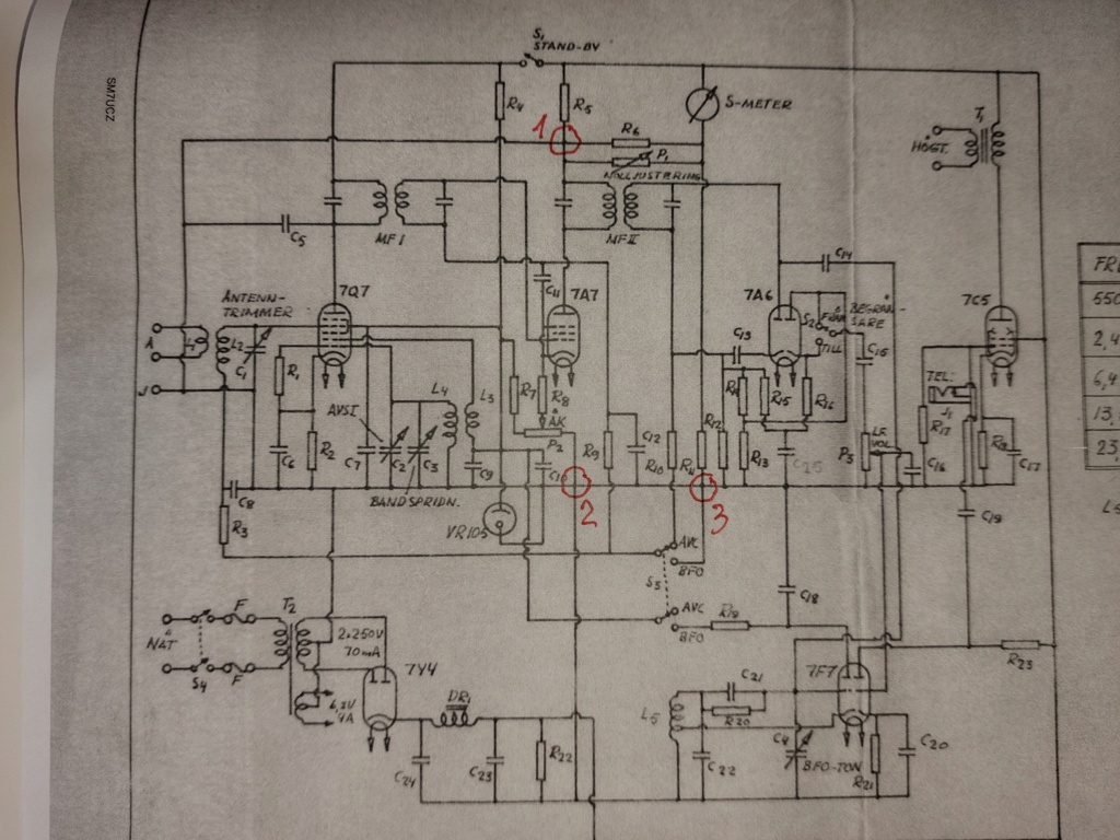
There is another strange resistor network there. It is hard to figure out how it works, moreover without part values. What is the SPDT switch next to the double diode for? Anyway, LF modulation and AVC voltage are taken from that tube.
VBR fron Ivan
VBR fron Ivan
Ivan- Posts : 794
Join date : 2012-11-25
Age : 64
Location : Praha, Czechia
Traffic receiver
![]() by LA1DEA Fri Jul 29, 2022 3:06 pm
by LA1DEA Fri Jul 29, 2022 3:06 pm
I guess there must be an issue regarding the double diode 7A6.
I think that the "first" catodes shoud bee grounded???
73 LA1DEA
I think that the "first" catodes shoud bee grounded???
73 LA1DEA
LA1DEA- Posts : 6
Join date : 2022-07-26
LA1DEA- Posts : 6
Join date : 2022-07-26
Re: Traffic receiver
![]() by Ivan Fri Jul 29, 2022 6:37 am
by Ivan Fri Jul 29, 2022 6:37 am
Hi,
such a great mistake like drawing several excessive resistors seems improbable. In any case, the S-meter is not crucial for the function of the RX. If you are going to repair/restore one, hold on the real circuitry instead of the schematic. If you want to make a free copy of the receiver, omit the S-meter or connect it as you consider the best.
VBR from Ivan
Ivan- Posts : 794
Join date : 2012-11-25
Age : 64
Location : Praha, Czechia
LA1DEA likes this post
Traffic receiver
![]() by LA1DEA Thu Jul 28, 2022 5:25 pm
by LA1DEA Thu Jul 28, 2022 5:25 pm
Thanks for respons
I dont think there should be an connection at pkt.1 because I cant see why the AVC signal has anything to do with the high voltage supply to the anode of 7A7.
I think that the AVC signal should go directly the the S-meter
73 LA1DEA
I dont think there should be an connection at pkt.1 because I cant see why the AVC signal has anything to do with the high voltage supply to the anode of 7A7.
I think that the AVC signal should go directly the the S-meter
73 LA1DEA
LA1DEA- Posts : 6
Join date : 2022-07-26
Re: Traffic receiver
![]() by Ivan Thu Jul 28, 2022 5:01 pm
by Ivan Thu Jul 28, 2022 5:01 pm
No, I am not sure. But R6 and P1 may be in parralel. I guess P1 is used during RX calibration only.
It looks like this schematic uses symbols of cross = connection, a small semicircle = no connection. Some other schematics use cross = no connection, cross with round dott = connection. It is rather confusing.
VBR from Ivan
It looks like this schematic uses symbols of cross = connection, a small semicircle = no connection. Some other schematics use cross = no connection, cross with round dott = connection. It is rather confusing.
VBR from Ivan
Ivan- Posts : 794
Join date : 2012-11-25
Age : 64
Location : Praha, Czechia
Traffic receiver
![]() by LA1DEA Thu Jul 28, 2022 9:08 am
by LA1DEA Thu Jul 28, 2022 9:08 am
Tanks for respons. Very good answare.
But are you shure about pkt 1? If there are a connection then R6 and P1 are in parallell?
73 LA1DEA
But are you shure about pkt 1? If there are a connection then R6 and P1 are in parallell?
73 LA1DEA
LA1DEA- Posts : 6
Join date : 2022-07-26
Re: Traffic receiver
![]() by Ivan Thu Jul 28, 2022 7:09 am
by Ivan Thu Jul 28, 2022 7:09 am
Hi,
it is quite a puzzle IMHO all three points shall be connected, but there is a mistake at the area of the intput.
R5, R6, R11 and P1 form a kind of bridge. The connection from R5/R6 shall lead to the point R3/C8 and not to the ground. This way the meter can show the AVC voltage in fact. The "J" is an external ground connection of the chassis, not connected with R5/R6/P1.
Point 2 is surely connected, it is the ground connection of the filtration capacitors and the BFO. I wonder why the center of the secondary of the power transformer is connected to the ground in another point than the filter...
Point 3 seems to be connected as well - it sets the AVC voltage to 0V when the BFO is in use (CW/SSB).
VBR from Ivan OK1SIP
it is quite a puzzle
R5, R6, R11 and P1 form a kind of bridge. The connection from R5/R6 shall lead to the point R3/C8 and not to the ground. This way the meter can show the AVC voltage in fact. The "J" is an external ground connection of the chassis, not connected with R5/R6/P1.
Point 2 is surely connected, it is the ground connection of the filtration capacitors and the BFO. I wonder why the center of the secondary of the power transformer is connected to the ground in another point than the filter...
Point 3 seems to be connected as well - it sets the AVC voltage to 0V when the BFO is in use (CW/SSB).
VBR from Ivan OK1SIP
Last edited by Ivan on Fri Jul 29, 2022 5:06 pm; edited 1 time in total
Ivan- Posts : 794
Join date : 2012-11-25
Age : 64
Location : Praha, Czechia
Traffic receiver
![]() by LA1DEA Wed Jul 27, 2022 1:25 pm
by LA1DEA Wed Jul 27, 2022 1:25 pm
Hi
I have a question regarding enclosen picture.
Is the a connetion on 1, 2 and 3?
If there are there connection on 1, then high voltage is shortcutted to ground.
If no connetcion then R6 and R11 are in parallell to ground.
I guess the are drawing fault in area around S-meter-
Hope anyone can help me?
73 LA1DEA
LA1DEA- Posts : 6
Join date : 2022-07-26
» SW receiver
» VHF CAVITY RECEIVER
» AM Reflex Rec
» Going to give the "lil" "Cigar box receiver" in Harry's site a whirl.
» 2m Receiver Idea
» VHF CAVITY RECEIVER
» AM Reflex Rec
» Going to give the "lil" "Cigar box receiver" in Harry's site a whirl.
» 2m Receiver Idea
Permissions in this forum:
You can reply to topics in this forum|
|
|