Please, help me with this intercom setup.
2 posters


Re: Please, help me with this intercom setup.
![]() by Ruud Mon Aug 04, 2014 8:57 pm
by Ruud Mon Aug 04, 2014 8:57 pm
OK, this one works! (The previous one didn't...)

Ruud- Posts : 130
Join date : 2012-11-26
Age : 68
Location : Haule, The Netherlands -

Re: Please, help me with this intercom setup.
![]() by OhMy Mon Aug 04, 2014 8:25 pm
by OhMy Mon Aug 04, 2014 8:25 pm
Click on "Enlarge this image" or "Click to see fullsize", and you should be able to see a bigger version of the image. There are some limitations for the unregistered users like me.
Here is a cropped piece of that image, showing the changes (diodes added in series for every OUTGOING connection in every station)

 " />
" />
Now all stations can talk to each other. I used LM358 instead of the original LM741 (I didn't have those).
Here is a cropped piece of that image, showing the changes (diodes added in series for every OUTGOING connection in every station)
" />Now all stations can talk to each other. I used LM358 instead of the original LM741 (I didn't have those).
OhMy- Guest
Re: Please, help me with this intercom setup.
![]() by Ruud Mon Aug 04, 2014 2:36 pm
by Ruud Mon Aug 04, 2014 2:36 pm
I can't see the picture!
Ruud- Posts : 130
Join date : 2012-11-26
Age : 68
Location : Haule, The Netherlands -
Re: Please, help me with this intercom setup.
![]() by OhMy Mon Aug 04, 2014 10:09 am
by OhMy Mon Aug 04, 2014 10:09 am
This is how I resolved the problem (with help of others' advice):
: <a href=)
 " />
" />
" />
OhMy- Guest
Re: Please, help me with this intercom setup.
![]() by OhMy Wed Jul 30, 2014 9:34 pm
by OhMy Wed Jul 30, 2014 9:34 pm
Hi, Harry, and thank you for replaying.
Thanks also for suggestions on solving the heating problem, but that will have to wait, till bigger problems are resolved.
 " />. In this case they work fine in both directions.
But as soon as I try to connect the third or fourth station like this " />, I'm unable to call station one from either station #2 or #3. In this case the voltage at the receiving station's #1 input is just about 2.8-3V instead of needed ~6V. It seems to me, that the paralleled outputs from Stations #2 and #3 are inhibiting each other.
Full wiring diagram of all four stations looks like this " />. I think it should be correct, but all stations are unable to call each other.
I hope the changes in your life will be for better.
Regards,
Janis
Thanks also for suggestions on solving the heating problem, but that will have to wait, till bigger problems are resolved.
This shouldn't be the case, because all four stations together consume just 70mA at 12V in an idle state, and I have noticed just 0.1V drop upon pressing the "talk" button.It can be that if your amplifier stages have too much current then the combined current for four stations is causing a voltage drop on the power line.
Yes, it is so, but with only two stations connected like thisIf the stage is correctly wired then the microphone amplifier should have about 1/2 the supply voltage on the output pin. When you press a button then that voltage should appear on the control line to the receiving station.
" />. In this case they work fine in both directions.But as soon as I try to connect the third or fourth station like this
" />, I'm unable to call station one from either station #2 or #3. In this case the voltage at the receiving station's #1 input is just about 2.8-3V instead of needed ~6V. It seems to me, that the paralleled outputs from Stations #2 and #3 are inhibiting each other.Full wiring diagram of all four stations looks like this
" />. I think it should be correct, but all stations are unable to call each other.I hope the changes in your life will be for better.
Regards,
Janis
OhMy- Guest
Re: Please, help me with this intercom setup.
![]() by admin Wed Jul 30, 2014 4:34 pm
by admin Wed Jul 30, 2014 4:34 pm
If the output transistors are heating then there is too much bias current through the base-bias diodes. The transistors should remain stone-cold. An alternative bias arrangement is to put a 4K7 pot and connect the ends to the C and E of a BC547 transistor. Connect the wiper to the base of the transistor. the C and E of the transistor can then be connected in place of the two bias diodes and you can adjust it to give you almost zero current through the PA transistors. In order to test you can simply short one of the two bias diodes and the transistors will run stone cold, but there may be a little distortion on low level audio.
It can be that if your amplifier stages have too much current then the combined current for four stations is causing a voltage drop on the power line.
If the stage is correctly wired then the microphone amplifier should have about 1/2 the supply voltage on the output pin. When you press a button then that voltage should appear on the control line to the receiving station.
the DC voltage before the speaker capacitor should also be zero until the talk button is pressed. Then it should hop up to 1/2 the supply voltage. These tests should enable you to isolate whether the fault is the sender or receiver station.
Another little test is to use a 4K7 resistor in series with a 1u0 capacitor and a pair of Sony walkman (MP3 player) headphones. Connect this between Gnd and a station control line and you should be able to hear the sent audio.
I am sorry but I do not have much time for investigating your circuit as I have some urgent things to do between now and next Tuesday. I am making big changes to my life.
best regards from Harry
_________________
Everything in this world is either bacon, or it isn't bacon
They say that money cannot bring you happiness, but if you have it then you can always buy more bacon

admin- Admin
- Posts : 1144
Join date : 2012-11-24
Age : 72
Location : Märsta, Sweden -
Please, help me with this intercom setup.
![]() by OhMy Tue Jul 29, 2014 8:47 pm
by OhMy Tue Jul 29, 2014 8:47 pm
Hi!
After searching for intercom schematics, I settled on this one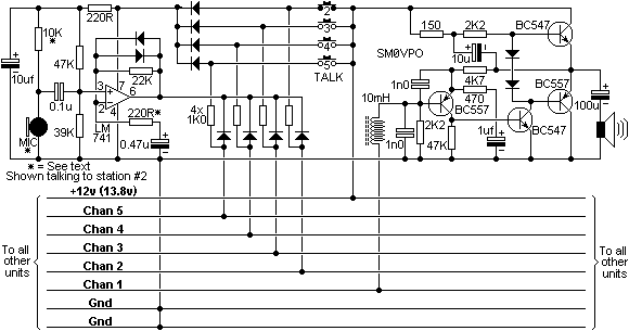 " /> from here - only one power source and independent stations. Next I built two test stations (in place of LM741 I used LM358 and all diodes are 4148)
  " /> , and they worked wonderfully, except for some output transistor heating.
So I built all four stations and wired them together as seen here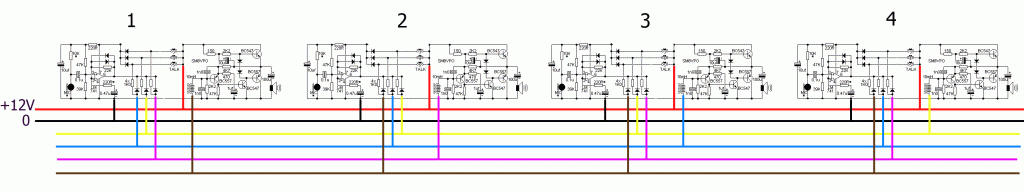 " /> . But all I got was nothing
  . Just some clicks were audible, when pressing corresponding buttons, but absolutely no voice transmissions.
Please, take a look at all this, if possible. I really would like to make it work.
Thank you very much.
After searching for intercom schematics, I settled on this one
" /> from here - only one power source and independent stations. Next I built two test stations (in place of LM741 I used LM358 and all diodes are 4148) " /> , and they worked wonderfully, except for some output transistor heating. So I built all four stations and wired them together as seen here
" /> . But all I got was nothing . Just some clicks were audible, when pressing corresponding buttons, but absolutely no voice transmissions.Please, take a look at all this, if possible. I really would like to make it work.
Thank you very much.
OhMy- Guest
Permissions in this forum:
You can reply to topics in this forum|
|
|