Receptor 7mhz válvulas se oye muy bajo


Ivan- Posts : 793
Join date : 2012-11-25
Age : 64
Location : Praha, Czechia
Re: Receptor 7mhz válvulas se oye muy bajo
![]() by vulkan Wed May 11, 2022 10:59 am
by vulkan Wed May 11, 2022 10:59 am
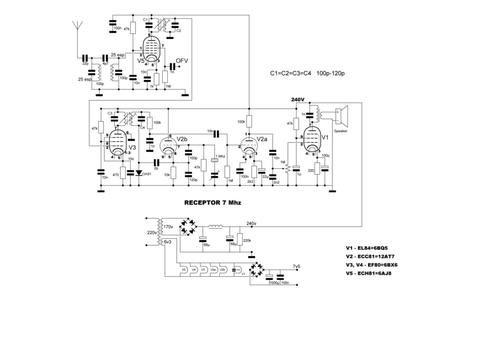
El ofv es de 8mhz a 8.2mhz, la frecuencia intermedia es de 1mhz
Lo he subido a otra web:
https://imgbox.com/zH3LxMIu
https://imgbox.com/NMmCFDoE
https://imgbox.com/WV7zGSob
vulkan- Posts : 16
Join date : 2020-06-07
Re: Receptor 7mhz válvulas se oye muy bajo
![]() by Ivan Tue May 10, 2022 9:36 pm
by Ivan Tue May 10, 2022 9:36 pm
use the icon "host an image" in the reply editor. Upload the photo as *.jpg to the associated server.
VBR from Ivan
Ivan- Posts : 793
Join date : 2012-11-25
Age : 64
Location : Praha, Czechia
Re: Receptor 7mhz válvulas se oye muy bajo
![]() by vulkan Tue May 10, 2022 7:59 pm
by vulkan Tue May 10, 2022 7:59 pm
¿como puedo insertar foto ?
vulkan- Posts : 16
Join date : 2020-06-07
Re: Receptor 7mhz válvulas se oye muy bajo
![]() by vulkan Wed Aug 04, 2021 7:34 pm
by vulkan Wed Aug 04, 2021 7:34 pm
He reformado el circuito, le he añadido otra F.I. y ahora funciona mucho mejor, aunque aún tengo que hacer los últimos ajustes.
https://i.servimg.com/u/f46/20/22/51/08/bloque10.jpg
vulkan- Posts : 16
Join date : 2020-06-07
Re: Receptor 7mhz válvulas se oye muy bajo
![]() by vulkan Tue Jul 27, 2021 11:02 am
by vulkan Tue Jul 27, 2021 11:02 am
vulkan- Posts : 16
Join date : 2020-06-07
Re: Receptor 7mhz válvulas se oye muy bajo
![]() by Glenndk Mon Jul 26, 2021 4:43 pm
by Glenndk Mon Jul 26, 2021 4:43 pm
vulkan wrote:Gracias por responder. El condensador de acoplamiento entre los LC , ya lo hice antes con 5pf pero no cambió nada. Los circuitos LC están separados.
Ahora voy a estudiar como hacer transformadores de FI
Hi Vulkan and 13inoxidable
Supplementary:
The missing coupling can be made by a small capacitor (must be able to handle circa 500V) between the EF80 anode and possibly the bottom (or top - I am not sure) of the second LC-circuit.
-
Regarding:
https://web.archive.org/web/20210723170629/https://i.servimg.com/u/f46/20/22/51/08/recep_13.jpg
Did you make a common (0V) connection between the VFO and the main circuit? (missing in schematic)
_________________
best regards,
Glenn / OZ1HFT
Glenndk- Posts : 114
Join date : 2017-01-06
Location : Copenhagen, Denmark -

Re: Receptor 7mhz válvulas se oye muy bajo
![]() by vulkan Mon Jul 26, 2021 4:21 pm
by vulkan Mon Jul 26, 2021 4:21 pm
Ahora voy a estudiar como hacer transformadores de FI
vulkan- Posts : 16
Join date : 2020-06-07
Re: Receptor 7mhz válvulas se oye muy bajo
![]() by Glenndk Mon Jul 26, 2021 2:38 pm
by Glenndk Mon Jul 26, 2021 2:38 pm
You might need to make your own coupling between the two LC-circuits at EF80 anode - it depends on the (internal) double LC-circuit design. Did you use to separate LC-circuits - or a monolitic double LC-circuit?
E.g. if there is missing coupling, the IF will be attenuated.
The missing coupling can be made by a small capacitor (must be able to handle circa 500V) between the EF80 anode and possibly the top of the second LC-circuit.
-
You can make your own tube IF LC-circuits:
DIY IF CANS FOR VALVES[=tubes].
Harry Lythall - SM0VPO:
http://sm0vpo.altervista.org/blocks/if-txfmr_tube_00.htm
https://web.archive.org/web/20201023140049/http://sm0vpo.altervista.org/blocks/if-txfmr_tube_00.htm
Make Your Own IF Transformers:
https://web.archive.org/web/20210120113118/http://www.angelfire.com/electronic/funwithtubes/IF_Can-1.html
-
Some IF-can/inductor information.
See below "Inductor experiments":
http://www.rfcandy.biz/communication/meny.html
RE-USING IF CANS
by Harry Lythall - SM0VPO:
http://sm0vpo.altervista.org/begin/cans-0.htm
_________________
best regards,
Glenn / OZ1HFT
Glenndk- Posts : 114
Join date : 2017-01-06
Location : Copenhagen, Denmark -
Re: Receptor 7mhz válvulas se oye muy bajo
![]() by vulkan Mon Jul 26, 2021 1:46 pm
by vulkan Mon Jul 26, 2021 1:46 pm
Para intentar solucionarlo he entendido que en los circuitos resonantes tengo que disminuir C y aumentar L ( manteniendo la frecuencia ) para poder acercarme a la impedancia de las válvulas.
Gracias por vuestras respuestas.
vulkan- Posts : 16
Join date : 2020-06-07
Re: Receptor 7mhz válvulas se oye muy bajo
![]() by Glenndk Sat Jul 24, 2021 11:16 am
by Glenndk Sat Jul 24, 2021 11:16 am
vulkan wrote:
...
¿ El filtro debería ser asi ?
https://i.servimg.com/u/f46/20/22/51/08/f_i_10.jpg
Gracias.
Yes, but you should somehow ensure the coupling coils has the propor impedances.
E.g.: I do not know the ECH81 anode output impedance at 5MHz:
http://www.r-type.org/exhib/aaa0036.htm
Datasheet:
u=22
S=2.4mA/V
Rout=u/S ca.= 9.2 kohm (source: https://www.diystompboxes.com/smfforum/index.php?topic=127298.0 and https://web.archive.org/web/20071010011219/http://www.turneraudio.com.au/tube-operation1.html )
Canode= 2.1pF Xc(5MHz) ca.= 15 kohm
E.g.: I do not know the EF80 gate input impedance at 5MHz:
http://www.r-type.org/exhib/aaq0439.htm
Is it Ri?
Datasheet:
Ri=500kohm@50MHz
Cg1= 2.6pF Xc(5MHz) ca.= 12 kohm
-
The procedure for ECH81 anode output:
The LC-circuit could be used so the loaded Q is Qunloaded/4 (3dB loss ! ? )
Qunloaded could be 100?
Then Qloaded=25
IF ca.= 5MHz; 150pF corresponds to Xc=212 ohm
Qloaded=25; Rtotal_load= 5300 ohm. (E.g. Rsource=10600 ohm - and Rload= 10600 ohm) (source: https://web.ece.ucsb.edu/Faculty/rodwell/Classes/ece218b/notes/Resonators.pdf , https://web.archive.org/web/20210507175006/https://web.ece.ucsb.edu/Faculty/rodwell/Classes/ece218b/notes/Resonators.pdf )
If Rsource= 9.2kohm @ 5MHz then you should decrease C in LC to e.g. 150pF (e.g. not changed) (9.2kohm/10kohm) ca.= 1 if Qloaded=25. (and increase coil inductance correspondingly)
(Canode is "absorbed" by the LC circuit and therefore will not load - but it only happens if a LC-circuit is directly connected to the anode) (if a coupling coil was used Ri=15 kohm - or lower!)
-
The procedure to match 4.7kohm:
If e.g. C=150pF and some L-coil with e.g. (just example) 30 windings.
Rlc= 9.2kohm
Rcoupling=4.7kohm
sqrt(4.7kohm/9.2kohm) = WINDINGScoupling/WINDINGScoilL
<=>
WINDINGScoilL x sqrt(4.7kohm/9.2kohm) = WINDINGScoupling
<=>
30 x sqrt(4.7kohm/9.2kohm) ca.= 21
-
The procedure at EF80 gate input:
Qloaded=25
IF ca.= 5MHz; 150pF corresponds to Xc=212 ohm
Qloaded=25; Rload= 500 kohm? or 15kohm? (properly higher at 5MHz?)
If Rin= 500kohm @ 5MHz then you should decrease C in LC to e.g. 3pF (500kohm/10kohm)=50 if Qloaded=25. (and increase coil inductance correspondingly)
3pF is too little I think (comments please):
You should decrease C in LC to e.g. maybe 10pF. Then Qunloaded will happen here, unless you put a resistor in parallel with the capacitor. (and increase coil inductance correspondingly)
(Cg1 is "absorbed" by the LC circuit and therefore will not load - but it only happens if a LC-circuit is directly connected to the gate) (if a coupling coil was used Ri=12 kohm - or lower!)
-
This procedure should also be employed at the ECH81 gate input. Decreasing C (and increase coil inductance correspondingly) in the LC circuits and maintaining the same antenna input impedance via tapping or a coupling coil, will yield "free" amplification.
-
Example with IF 10.7MHz:
https://www.roehrentechnik.de/html/zf-bandfilter.html
Quote: "...
Speziell für Röhrenschaltungen geeignete ZF-Bandfilter mit entsprechenden LC-Verhältnissen und Resonanzwiderständen stellen wir in 2 Ausführungen her:
...
10.7MHz....33pF
..."
-
Please note:
Please beware: Because tubes uses high voltages, the isolation between coils must be able to handle 500V - or you yourself must make a circuit design that do not let the coil-to-coil have high voltages.
You actually do not need two coupled LC circuits at 5MHz between ECH81 and EF80. One of the LC circuits can be replaced by a coupling coil. (you will get better skirt attenuation though - with the propor design)
(at 455kHz it could be a good choice to ensure wide passband)
But - The second LC "absorb" Cg1 and therefore makes it possible to get higher amplification. Good design choice.
But - The first LC "absorb" Canode and therefore makes it possible to get higher amplification. Good design choice.
At 5MHz one LC circuits has -3dB at 5MHz/Qloaded=5MHz/25=200kHz
If a triode was used as an IF amplifier, the circuit could be unstable. But because a pentode has a very low Canode-to-gate1 the IF amplifier should be stable.
(Any comments please? Is this correct?)
-
Purpose: Maximize amplification
Maybe one high loaded Q LC-circuits with a coupling coil - with the 5MHz crystal filter in between - could be combined with a low loaded Q L-section (series L parallel C) high-impedance matching to the gate (have never tried it - do not know if it works):
Page 24 right, page 29:
http://www.clivepoole.com/wp-content/uploads/2016/07/Lecture-9-Lumped-Element-Matching-Networks.pdf
https://www.qsl.net/va3iul/Impedance_Matching/Impedance_Matching.pdf
-
Use EF184 instead of EF80?:
EF184:
http://www.r-type.org/exhib/aaq0492.htm
Datasheet:
Ri=500kohm@50MHz
Cg1= 10pF
u=60 (?)
S=15mA/V
Rout=u/S ca.= 4 kohm (source: https://www.diystompboxes.com/smfforum/index.php?topic=127298.0 )
Canode= 3pF
Gm=15mA/V is higher than EF80.
-
Measures against VHF/UHF parasitics:
Put 10-100 ohm (but not higher in IF-amps) resistor in series with the grid and anode:
https://www.diyaudio.com/forums/tubes-valves/103368-anode-stoppers.html
https://www.aikenamps.com/index.php/grid-resistors-why-are-they-used
Quote: "...
In order to take advantage of the parasitic suppression benefits of these grid resistors, they must be placed as close as possible to the socket pin of the tube, preferably soldered directly to the pin with a very short lead.
..."
Improved anode parasitic suppression for modern amplifier tubes:
https://www.robkalmeijer.nl/techniek/electronica/radiotechniek/hambladen/qst/1988/10/page36/index.html
Grid stoppers:
https://www.vintage-radio.net/forum/showthread.php?t=135324
Quote: "...
If grid feeds have capacitance to ground (real capacitors or just stray capacitance) and a bit of lead length gives some inductance, plus if cathodes are decoupled to ground (or hard grounded) and anode circuits have stray-C to ground, there is the possibility that you've created an RF oscillator using the internal capacitances of the valve (transistors have the same problem)
This problem exists in just the components and wiring around the valve. The valve doesn't have to be in an audio amplifier and it's nothing to do with whether an amplifier has overall negative feedback or not (that's a different oscillatory mechanism and does have formulae).
...
So you see grid stoppers get used first, and then anode droppers get added if stronger measures are needed.
..."
-
(Any comments please?)
-
Further down there is a link to a vintage tube book.
Many american old books did not have their copyright renewed before 1964:
http://www.tubebooks.org/technical_books_online.htm
Quote: "...
I've found that most of the technical books published before about 1964 never had their copyrights renewed, so now are in the public domain. So I am endeavoring to digitize and post some selected books relating to the "vacuum tube age" of electronics here.
...
I have checked to the best of my ability to confirm that these works have expired copyrights and are now in the public domain. If you have information to the contrary, please contact me at:
..."
How Can I Tell Whether a Copyright Was Renewed?:
http://onlinebooks.library.upenn.edu/renewals.html
Citat: "...
First of all, you need to know when renewal matters. In the US, books published before 1964 had to get their copyrights renewed at the Library of Congress Copyright Office in their 28th year, or they'd fall into the public domain. Some books originally published outside the US by non-Americans are exempt from this requirement, and in fact some such books had their copyrights restored recently. If you need to know more about the rules for books published outside the US, see this page from the Copyright Office, explaining recent changes in copyright law imposed by GATT. Basically a work is exempt from renewal requirements if all of the following conditions apply:
At least one author was a citizen or resident of a foreign country (outside the US) that's a party to the applicable copyright agreements. (Almost all countries are parties to these agreements.)
The work was still under copyright in at least one author's "home country" at the time the GATT copyright agreement went into effect for that country (1 January 1996 for most countries).
The work was first published abroad, and not published in the United States until at least 30 days after its first publication abroad.
If you can prove any of these conditions don't apply, and the work was originally published or copyrighted before 1964, then the work had to be renewed in order to stay copyrighted in the US.
..."
1953, Radiotron designer's handbook:
Chapter 26 Intermediate frequency amplifier:
http://www.tubebooks.org/books/rdh4.pdf
backup:
https://web.archive.org/web/20210708135027/http://www.tubebooks.org/books/rdh4.pdf
Last edited by Glenndk on Sat Jul 31, 2021 10:37 pm; edited 1 time in total
_________________
best regards,
Glenn / OZ1HFT
Glenndk- Posts : 114
Join date : 2017-01-06
Location : Copenhagen, Denmark -
Re: Receptor 7mhz válvulas se oye muy bajo
![]() by vulkan Sat Jul 24, 2021 9:29 am
by vulkan Sat Jul 24, 2021 9:29 am
Voy a sustituir la resistencia de 4k7 por un L-C de 5mhz, y si es necesario también sustituir la ECC81 por ECC83.
Por lo que he podido comprobar creo que el problema no está en la BF, porque he probado con un amplificador de audio externo, creo que el problema es la F.I.
¿ El filtro debería ser asi ?
https://i.servimg.com/u/f46/20/22/51/08/f_i_10.jpg
Gracias.
vulkan- Posts : 16
Join date : 2020-06-07
Re: Receptor 7mhz válvulas se oye muy bajo
![]() by Glenndk Sat Jul 24, 2021 8:32 am
by Glenndk Sat Jul 24, 2021 8:32 am
vulkan wrote:Buenas tardes.
Volumen de audio muy bajo y el circuito LC de entrada es un filtro pasa-banda.
Sí está inspirado en ese circuito
Hi Harry, Vulkan and 13inoxidable
Harry do you have any suggestion what the voltage levels / amplification at each stage should be? Other any comments?
-
Please be very careful - 240V is dangerous, when measuring. E.g. unplug the receiver when placing probe wires. (discount security; keep one in the pocket - and the other placing probes, when working with live circuits):
Working with High Voltages:
https://www.nutsvolts.com/magazine/article/working-with-high-voltages
backup:
https://web.archive.org/web/20210724070051/https://www.nutsvolts.com/magazine/article/working-with-high-voltages
Quote: "...A comment in the digital Nuts & Volts issue by Larry Reynolds K4MLA noted an old and effective rule: “When working with high voltage equipment, keep one hand in your pocket.”...If you’re wearing pants and shoes with insulating soles, the current path has a much higher resistance so less current will flow. Better yet, the path from a hand to a foot doesn’t go through the heart. Make it a habit to work one-handed around energized equipment and you’ll be a step ahead of electricity...."
http://examenes.np3ir.com/Material%20de%20Estudio-Estudiantes-Final-General.pdf
backup:
https://web.archive.org/web/20210724065811/http://examenes.np3ir.com/Material%20de%20Estudio-Estudiantes-Final-General.pdf
"...
[page 412]
* Mantén una mano en tu bolsillo cuando pruebes equipo energizado
* Viste zapatos con suela aislada
* Remueve toda la joyería innecesaria
..."
-
You ought to also make a 50 ohm antenna input via a tapping of the L-coil for measurements (will also give "free" voltage amplification for 50 ohm antennas). (you can afterwards choose the antenna input you want to - high impedance or low impedance.) Your high impedance input via 22pF ought to have a 1Mohm or 100kohm to ground to ensure that the capacitor is not shorted by a high voltage arc. Comments?
Please check - if possible - the voltage levels throughout the AF stages. E.g. at 1, 10 , 100mV 1kHz AF input just before V2a at the point at 1nF, 10nF and 100kohm.
Please check - if possible - the RF/AF voltage levels throughout the receiver. E.g. at 50uV@50ohm (ca.=S9) at 7.1MHz antenna input.
If the above works half the voltage (again and again until 1.6uV (ca.=S4) - or until nothing can be registered):
Please check - if possible - the RF/AF voltage levels throughout the receiver. E.g. at 25uV (ca.=S8) at 7.1MHz antenna input.
( https://en.wikipedia.org/wiki/S_meter#Examples or https://es.wikipedia.org/wiki/S-meter#Escala_%22S%22 )
-
Here is a cautious suggestion. The 4k7 ohm can be exchanged for an IF-filter - low side to the crystal ladder filter - and the LC to the gate. That will give some "free" voltage amplification - if needed?
But be aware of the propor crystal ladder filter termination at both input and output.
Ideally you should also use a this diplexer at both input and output of the crystal ladder filter (what is your opinion Harry and others? Is it overkill here?):
Mixer Terminations (diplexer):
https://www.qsl.net/g3oou/mixerterminations.html
https://web.archive.org/web/20180901161510/https://www.qsl.net/g3oou/mixerterminations.html
-
(if you need more RF amplification you could insert an EF80 IF-stage more. The higher IF the lower amplification - you chose 5MHz. But the measurements will reveal if needed. Maybe the low AF is caused by a problem somewhere? The measurements will reveal it?)
(i have a suggestion for CW/SSB AGC circuit if you later are interested)
Last edited by Glenndk on Sat Jul 24, 2021 10:26 am; edited 13 times in total
_________________
best regards,
Glenn / OZ1HFT
Glenndk- Posts : 114
Join date : 2017-01-06
Location : Copenhagen, Denmark -
Re: Receptor 7mhz válvulas se oye muy bajo
![]() by admin Fri Jul 23, 2021 11:47 pm
by admin Fri Jul 23, 2021 11:47 pm
My HF receiver http://sm0vpo.altervista.org/rx/tube-rx.htm#rx was inspired in the late 70s/early 80s by the Heathkit RG1, long before the https://i.servimg.com/u/f46/20/22/51/08/recep_13.jpg was published.
I used to have a Heathkit RG1 in the 60s and it folowed me around the world when I worked for the British military. I cannot remember how I eventually lost it but it was around 1975.
As regards the "low volume" I presume that you are meaning the receiver has a low gain. A good way to improve that is to simply replace the ECC81 (V-gain = 30) with an ECC83 (v-gain = 100). The ECC is intended for audio due to the high Anode to Grid capacitance, but in this application used as an intermediate frequency amplifier (less than 1MHz) it works very well.
V2b is a 5MHz oscillator and that should not be a problem at 5MHz. V2a is an audio amplifier so the ECC83 will give you 3x the gain. The heptode mixer does not give much (if any) conversion gain so all the IF gain is really due to the one EF80 and audio amplification.
Best regards from Harry - SM0VPO
Hola Vulkan,
Mi receptor de HF http://sm0vpo.altervista.org/rx/tube-rx.htm#rx se inspiró a finales de los 70 y principios de los 80 en el Heathkit RG1, mucho antes del https://i.servimg.com/u /f46/20/22/51/08/recep_13.jpg fue publicado.
Solía tener un Heathkit RG1 en los años 60 y me siguió por todo el mundo cuando trabajaba para el ejército británico. No recuerdo cómo finalmente lo perdí, pero fue alrededor de 1975.
En cuanto al "volumen bajo", supongo que quiere decir que el receptor tiene una ganancia baja. Una buena forma de mejorarlo es simplemente reemplazar el ECC81 (ganancia V = 30) con un ECC83 (ganancia V = 100). El ECC está diseñado para audio debido a la alta capacitancia del ánodo a la red, pero en esta aplicación utilizada como amplificador de frecuencia intermedia (menos de 1MHz) funciona muy bien.
V2b es un oscilador de 5MHz y eso no debería ser un problema a 5MHz. V2a es un amplificador de audio, por lo que el ECC83 le dará 3 veces la ganancia. El mezclador heptode no da mucha (si alguna) ganancia de conversión por lo que toda la ganancia de FI se debe realmente al EF80 y la amplificación de audio.
Saludos cordiales de Harry - SM0VPO
_________________
Everything in this world is either bacon, or it isn't bacon
They say that money cannot bring you happiness, but if you have it then you can always buy more bacon

admin- Admin
- Posts : 1144
Join date : 2012-11-24
Age : 72
Location : Märsta, Sweden -
Re: Receptor 7mhz válvulas se oye muy bajo
![]() by vulkan Fri Jul 23, 2021 7:44 pm
by vulkan Fri Jul 23, 2021 7:44 pm
Volumen de audio muy bajo y el circuito LC de entrada es un filtro pasa-banda.
Sí está inspirado en ese circuito
vulkan- Posts : 16
Join date : 2020-06-07
Re: Receptor 7mhz válvulas se oye muy bajo
![]() by Glenndk Fri Jul 23, 2021 7:04 pm
by Glenndk Fri Jul 23, 2021 7:04 pm
vulkan wrote:https://i.servimg.com/u/f46/20/22/51/08/recep_13.jpg
Backup:
https://web.archive.org/web/20210723170629/https://i.servimg.com/u/f46/20/22/51/08/recep_13.jpg
I guess that it is inspired by this circuit - right Harry, Vulcan and 13inoxidable?:
ALL VALVE RECEIVER
by Harry Lythall - SM0VPO
http://sm0vpo.altervista.org/rx/tube-rx.htm#rx
-
13inoxidable circuit uses:
IF ca.= 5MHz 150pF corr. to Xc=212 ohm
(instead of Harry's IF=455kHz, 250pF(guess) corr. to Xc=1400 ohm). Correction: (Harry's IF=455kHz, 100pF corr. to Xc=3500 ohm)
the antenna dual-LC covers the interval 7.0-7.2MHz without adjustment?
The VFO is based on a circuit with Si570 - and covers 12.0-12.2MHz.
The VFO output impedance and output signal level - what are they?
Last edited by Glenndk on Sat Jul 24, 2021 11:27 am; edited 4 times in total
_________________
best regards,
Glenn / OZ1HFT
Glenndk- Posts : 114
Join date : 2017-01-06
Location : Copenhagen, Denmark -
Re: Receptor 7mhz válvulas se oye muy bajo
![]() by Ivan Fri Jul 23, 2021 6:44 pm
by Ivan Fri Jul 23, 2021 6:44 pm
" but it sounds very low" means"
low volume of audio, or
low pitch sound, or
plays in the lower part of the band only
or what?
BR from Ivan OK1SIP
Ivan- Posts : 793
Join date : 2012-11-25
Age : 64
Location : Praha, Czechia
admin likes this post
Re: Receptor 7mhz válvulas se oye muy bajo
![]() by vulkan Fri Jul 23, 2021 6:04 pm
by vulkan Fri Jul 23, 2021 6:04 pm
vulkan- Posts : 16
Join date : 2020-06-07
admin likes this post
Re: Receptor 7mhz válvulas se oye muy bajo
![]() by vulkan Fri Jul 23, 2021 5:17 pm
by vulkan Fri Jul 23, 2021 5:17 pm
vulkan- Posts : 16
Join date : 2020-06-07
admin likes this post
Receiver 7mhz tubes sounds very low
![]() by Glenndk Fri Jul 23, 2021 3:20 pm
by Glenndk Fri Jul 23, 2021 3:20 pm
I have mounted the general coverage receiver modified to receive only 7mhz, but it sounds very low.
I have checked the BF stage. with a bf generator and it's fine. and all other adjustments are made with RF generator.
See if you can help me where I was wrong. Thanks.
Attached schematic [missing; spanish: desaparecido ]
_________________
best regards,
Glenn / OZ1HFT
Glenndk- Posts : 114
Join date : 2017-01-06
Location : Copenhagen, Denmark -
admin likes this post
Receptor 7mhz válvulas se oye muy bajo
![]() by 13inoxidable Fri Jul 23, 2021 12:46 pm
by 13inoxidable Fri Jul 23, 2021 12:46 pm
He comprobado la etapa de BF. con un generador de bf y está bien. y todos los demás ajustes están hechos con generador de RF.
Aver si me podéis ayudar en que me he equivocado. Gracias.
Adjunto esquema
13inoxidable- Guest