MOD SWR to POWER METER QUESTIONS
+2
Ivan
indrasung
6 posters


Re: MOD SWR to POWER METER QUESTIONS
![]() by Glenndk Tue Mar 05, 2024 11:16 am
by Glenndk Tue Mar 05, 2024 11:16 am
sm0vpo wrote:
...
I have just searched my homepages for a broadband modification to a cheap VSWR meter as in this thread. I have already built the project, written the HTML files, but apparently forgotten to upload them. I will have a good look for them after the "Christian Festival of Spending" is over.
Best regards - Harry - sm0vpo
...
Hi Harry
How about this - no SMD necessary:
W7EL, Feb, 1990 issue of QST magazine.
A simple and accurate QRP Directional Wattmeter.
Make a few small enhancements to the Bruene watmeter and diode detector, and you have a directional wattmeter that's simple, portable, and accurate from 10 watts down to 5 milliwatts!:
http://www.qsl.net/kl7jef/QRP%20Directional%20Wattmeter.pdf
backup:
https://web.archive.org/web/20170313085539/http://www.qsl.net/kl7jef/QRP%20Directional%20Wattmeter.pdf
A Bruene Bridge Directional Coupler with DC Output (V2):
https://electronicprojectsforfun.wordpress.com/rf-module-gallery/swr-bridges/a-bruene-bridge-directional-coupler-with-dc-output-v2/
backup:
https://web.archive.org/web/20200906013415/https://electronicprojectsforfun.wordpress.com/rf-module-gallery/swr-bridges/a-bruene-bridge-directional-coupler-with-dc-output-v2/
Quote: "...
Transmission is fairly OK, only 0.5dB down from ca. 1MHz to 170MHz. The sweet spot is ca. 30MHz, with 0.25dB thru attenuation. Reflection also OK, better than 20dB up to 350MHz. Fair enough. This part is definitely usable up to the 2m band.
...
At the end of the day, we can state the following:
It works. Matched VSWR is accurate to 3% up to the 2m band.
..."
February 4, 2015, More Notes on Directional Couplers for HF -- the Bruene Coupler, Part 1:
https://k6jca.blogspot.com/2015/02/more-notes-on-directional-couplers-for_4.html
backup:
https://web.archive.org/web/20240127135028/https://k6jca.blogspot.com/2015/02/more-notes-on-directional-couplers-for_4.html
Quote: "...
Here's an interesting take on the Bruene Coupler, published by W7EL in the Feb, 1990 issue of QST magazine.
Per the article, this version has +/- 7% accuracy over the range of 1 to 432 MHz. Quite impressive!
...
The only negative that I can see with respect to the design is that you need to wind 3 transformers!
..."
You could use more or less of the circuit from ( http://karinya.net/g3txq/swr_meter/schematic.jpg ), with the QRP Directional Wattmeter.
best regards,
Glenn / OZ1HFT
Glenndk- Posts : 114
Join date : 2017-01-06
Location : Copenhagen, Denmark -

Re: MOD SWR to POWER METER QUESTIONS
![]() by Andrew Wed Dec 27, 2023 6:29 pm
by Andrew Wed Dec 27, 2023 6:29 pm
Harry, as for the metering circuit, have a look at this
https://karinya.net/g3txq/swr_meter/
https://karinya.net/g3txq/swr_meter/schematic.jpg
not only it's rather simple, but it offers very good precision, just check the AD8307 datasheet and you'll see it
https://karinya.net/g3txq/swr_meter/
https://karinya.net/g3txq/swr_meter/schematic.jpg
not only it's rather simple, but it offers very good precision, just check the AD8307 datasheet and you'll see it
Andrew- Posts : 150
Join date : 2021-03-24
Age : 63
Location : Italy
sm0vpo likes this post
Re: MOD SWR to POWER METER QUESTIONS
![]() by Ivan Fri Dec 22, 2023 2:27 pm
by Ivan Fri Dec 22, 2023 2:27 pm
Hi Harry,sm0vpo wrote:This is a really interesting thread. I have now got an idea:
I have always wanted a two-pointer VSWR meter, but the mechanics were always against me to make a reasonable job, but not now
I have a 3D printer, a computer and a scanner printer. I also have PhotoShop. All I need to do is to resize this picture to get the exact mounting positions and the scale for my VSWR meter. Then I can drill (or print) a plastic panel to suit the meter movements, and glue the image below on it.
It may be necessary to extend the meter pointers and add a bit of solder blob to the counter-balance so the pointers are not affected by gravity (that is at the little X at the hub of the meter movement). If the meter movements are cannibalised from a couple of cheap $5 analogue multimeters then you may not have to extend the pointers
Best regards - Harry
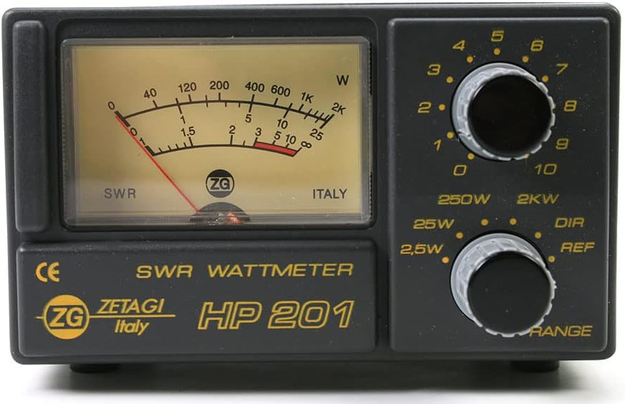
or you can get one here (more sellers offer it for nearly the same price).
" One small comment, if the watt values here are to remain, then one can physically reverse the IN and OUT terminals to get a 300W or 60W range. "
But the red lines of equal SWR would be reversed in the 60W case.
Making a wideband direction divider is the most tough task when designing an all band HF SWR meter.
I am doing some basic experiments with the ESP32 MCU. It is amazing what this little beast can do! One ESP32, a cheap OLED display and good shielding could replace the two-needle meter, adding a WiFi connected web server. You could have the SWR meter directly at the antenna and read the values remotely on your smartphone.
VBR from Ivan
Ivan- Posts : 793
Join date : 2012-11-25
Age : 64
Location : Praha, Czechia
sm0vpo likes this post
Re: MOD SWR to POWER METER QUESTIONS
![]() by sm0vpo Fri Dec 22, 2023 1:14 pm
by sm0vpo Fri Dec 22, 2023 1:14 pm
This is a really interesting thread. I have now got an idea:
I have always wanted a two-pointer VSWR meter, but the mechanics were always against me to make a reasonable job, but not now
I have a 3D printer, a computer and a scanner printer. I also have PhotoShop. All I need to do is to resize this picture to get the exact mounting positions and the scale for my VSWR meter. Then I can drill (or print) a plastic panel to suit the meter movements, and glue the image below on it.
It may be necessary to extend the meter pointers and add a bit of solder blob to the counter-balance so the pointers are not affected by gravity (that is at the little X at the hub of the meter movement). If the meter movements are cannibalised from a couple of cheap $5 analogue multimeters then you may not have to extend the pointers
The forward meter can be fitted with a shunt so that the same voltage divider can be used for the 300W forward and 60W reflected. Alternatively use PhotoShop to change the scale for other values.
I will shortly have a lot of time on my hands, even with a lady friend, so I may christen my retirement with this project before I continue with some older (unfinished) projects.
One small comment, if the watt values here are to remain, then one can physically reverse the IN and OUT terminals to get a 300W or 60W range. Use a transmission line transformer and it will not be frequency conscious.
I have just searched my homepages for a broadband modification to a cheap VSWR meter as in this thread. I have already built the project, written the HTML files, but apparently forgotten to upload them. I will have a good look for them after the "Christian Festival of Spending" is over.
Best regards - Harry - sm0vpo
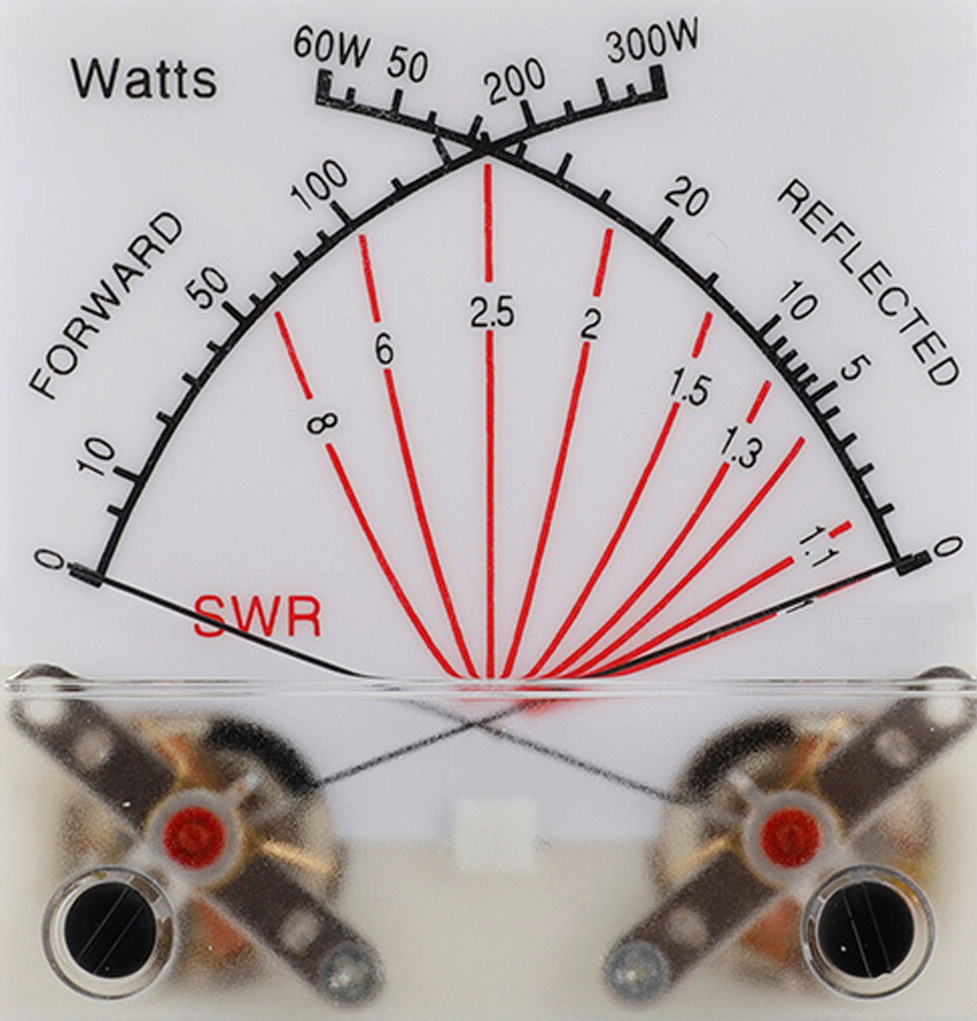
PS - This is the VSWR meter that I "linearised":
I have always wanted a two-pointer VSWR meter, but the mechanics were always against me to make a reasonable job, but not now
I have a 3D printer, a computer and a scanner printer. I also have PhotoShop. All I need to do is to resize this picture to get the exact mounting positions and the scale for my VSWR meter. Then I can drill (or print) a plastic panel to suit the meter movements, and glue the image below on it.
It may be necessary to extend the meter pointers and add a bit of solder blob to the counter-balance so the pointers are not affected by gravity (that is at the little X at the hub of the meter movement). If the meter movements are cannibalised from a couple of cheap $5 analogue multimeters then you may not have to extend the pointers
The forward meter can be fitted with a shunt so that the same voltage divider can be used for the 300W forward and 60W reflected. Alternatively use PhotoShop to change the scale for other values.
I will shortly have a lot of time on my hands, even with a lady friend, so I may christen my retirement with this project before I continue with some older (unfinished) projects.
One small comment, if the watt values here are to remain, then one can physically reverse the IN and OUT terminals to get a 300W or 60W range. Use a transmission line transformer and it will not be frequency conscious.
I have just searched my homepages for a broadband modification to a cheap VSWR meter as in this thread. I have already built the project, written the HTML files, but apparently forgotten to upload them. I will have a good look for them after the "Christian Festival of Spending" is over.
Best regards - Harry - sm0vpo
PS - This is the VSWR meter that I "linearised":
sm0vpo- Admin
- Posts : 110
Join date : 2013-03-26
Age : 72
Location : Märsta, Sweden
Re: MOD SWR to POWER METER QUESTIONS
![]() by Ivan Tue Dec 19, 2023 8:03 am
by Ivan Tue Dec 19, 2023 8:03 am
Hi,
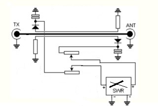
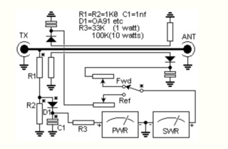
you were probably confused by the fact that the schematic includes two separate devices: a power meter and a SWR meter. The switch is used by the SWR meter only. If you want to use a two-needle SWR meter, do it like this:
You can eventually omit the PWR meter part at all:
VBR from Ivan OK1SIP
you were probably confused by the fact that the schematic includes two separate devices: a power meter and a SWR meter. The switch is used by the SWR meter only. If you want to use a two-needle SWR meter, do it like this:
You can eventually omit the PWR meter part at all:
VBR from Ivan OK1SIP
Ivan- Posts : 793
Join date : 2012-11-25
Age : 64
Location : Praha, Czechia
sm0vpo likes this post
MODIFY AN SWR METER TO READ RF POWER
![]() by Alexander Mon Dec 18, 2023 8:24 pm
by Alexander Mon Dec 18, 2023 8:24 pm
Hi Ivan,
thnaks for the fast reply on my question about the cross-needle meter.
Yup, you're right, the cross-needle meter is a system of two meters in one singel casing. Thus a total of 4 connections (twice '-' and twice '+').
But the difficult part for me is the switch in the schematic diagram.
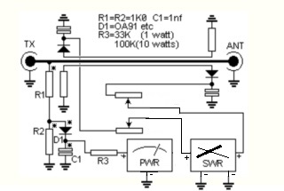
In the diagram the switch is in the FWD position, thus showing the FWD power.
No problem so far.
If I use the switch I can see the SWR. Great.But I can't read to meters at the same time I think.
What I understand from the drawing is that only one meter at a time can be read.
That's why I like to use a cross-needle meter. To read two meters at once.
But then the switch must be removed.
Am I correct to say that to use two meters, I leave the switch in the FWD-position (or just make a shortcut at that point) and copnect the
REF-postion to the '-'of both meters (ground)?
10 minutes later....
Think I got a simple solution:
Remove the switch.
For the REF-part, connect the cathode of the left diode via the potentiometer to the '-'of the left meter (GROUND).
For the FWD-part, add R1, R2, R3, D1, C1 to the right side and connect the cathode of the right diode via de potentiometer to ground.
thnaks for the fast reply on my question about the cross-needle meter.
Yup, you're right, the cross-needle meter is a system of two meters in one singel casing. Thus a total of 4 connections (twice '-' and twice '+').
But the difficult part for me is the switch in the schematic diagram.
In the diagram the switch is in the FWD position, thus showing the FWD power.
No problem so far.
If I use the switch I can see the SWR. Great.But I can't read to meters at the same time I think.
What I understand from the drawing is that only one meter at a time can be read.
That's why I like to use a cross-needle meter. To read two meters at once.
But then the switch must be removed.
Am I correct to say that to use two meters, I leave the switch in the FWD-position (or just make a shortcut at that point) and copnect the
REF-postion to the '-'of both meters (ground)?
10 minutes later....
Think I got a simple solution:
Remove the switch.
For the REF-part, connect the cathode of the left diode via the potentiometer to the '-'of the left meter (GROUND).
For the FWD-part, add R1, R2, R3, D1, C1 to the right side and connect the cathode of the right diode via de potentiometer to ground.
Last edited by Alexander on Mon Dec 18, 2023 8:42 pm; edited 1 time in total (Reason for editing : New ideas)
Alexander- Posts : 1
Join date : 2023-12-18
sm0vpo likes this post
Re: MOD SWR to POWER METER QUESTIONS
![]() by Ivan Mon Dec 18, 2023 8:04 pm
by Ivan Mon Dec 18, 2023 8:04 pm
Hi Alexander,
to be honest, I have never played with a cross-needle meter, so I may be absolutely wrong. I suppose it has two microammeter systems, each moving one needle. Each of the systems would be connected to one diode, so that one needle shows the FWD power and the other the REF one.
VBR from Ivan OK1SIP
to be honest, I have never played with a cross-needle meter, so I may be absolutely wrong. I suppose it has two microammeter systems, each moving one needle. Each of the systems would be connected to one diode, so that one needle shows the FWD power and the other the REF one.
VBR from Ivan OK1SIP
Ivan- Posts : 793
Join date : 2012-11-25
Age : 64
Location : Praha, Czechia
MODIFY AN SWR METER TO READ RF POWER
![]() by Alexander, PE1JUZ Mon Dec 18, 2023 7:42 pm
by Alexander, PE1JUZ Mon Dec 18, 2023 7:42 pm
I had the same question as previous person (100W output).
But my new question is:
I like to change the SWR-PWR.GIF with one single cross-neelde meter in stead of two meters.
In that case I should remove the FWD-REV stwitch and connect the right hand diode to the SWR-meter,
but....where to connect the left hand diode?
Maybe someone can solve tjis 'problem'.
Alexander, PE1JUZ- Guest
Re: MOD SWR to POWER METER QUESTIONS
![]() by Ivan Wed Apr 12, 2023 8:06 am
by Ivan Wed Apr 12, 2023 8:06 am
Hi,
the RF voltage on a matched 50 ohm line is slightly more than 70V at 100W. The toal power lost on R1 and R2 is therefore 2,5W, i.e. 1,25W each. Use 3W or 5W low inductance resistors (avoid wirewound types ). The power loss on R3 is negligible. The value of R3 depends on the internal resistance of the microammeter used.
VBR from Ivan OK1SIP
Ivan- Posts : 793
Join date : 2012-11-25
Age : 64
Location : Praha, Czechia
sm0vpo likes this post
MOD SWR to POWER METER QUESTIONS
![]() by indrasung Wed Apr 12, 2023 7:32 am
by indrasung Wed Apr 12, 2023 7:32 am
Hello
What is the power rating of R1 and R2 (@ 1K ), R3 for measuring 100Watt transmitter ?
What is the value and power rating of R3 for measuring 100 Watt transmitter ?
Note : assume the meter sensitivity around 250 to 500 uA.
Thanks
What is the power rating of R1 and R2 (@ 1K ), R3 for measuring 100Watt transmitter ?
What is the value and power rating of R3 for measuring 100 Watt transmitter ?
Note : assume the meter sensitivity around 250 to 500 uA.
Thanks
indrasung- Posts : 6
Join date : 2023-04-12
» AD8307 power meter
» Vu meter, RF probe, GDO queries
» 250mW 40 Meter AM Transmitter
» Field strength meter
» grid dip meter frequency pulling
» Vu meter, RF probe, GDO queries
» 250mW 40 Meter AM Transmitter
» Field strength meter
» grid dip meter frequency pulling
Permissions in this forum:
You can reply to topics in this forum|
|
|