Converting 500mW QRP amplifier to VHF amplifier


Re: Converting 500mW QRP amplifier to VHF amplifier
![]() by dare4444 Mon May 15, 2023 3:18 pm
by dare4444 Mon May 15, 2023 3:18 pm
Suman wrote:Hello Joy,
I am glad to know that you can speak Bengali. It is my first language. Thank you for the information you provided to me. I have downloaded LTspice as you mentioned me to do. But it is new to me to operate. So, it will take time to get used to LTspice. Thanks for diagrams you attached with your last message. Hope it will be helpful to me and will give me food for thought. I have already collected your diagram which is given below
Your approch to use simple low power Transistors impresses me. That's why, you are my inspiration. Have a good time.
With thanks,
Suman
Whatsapp me +919369610798
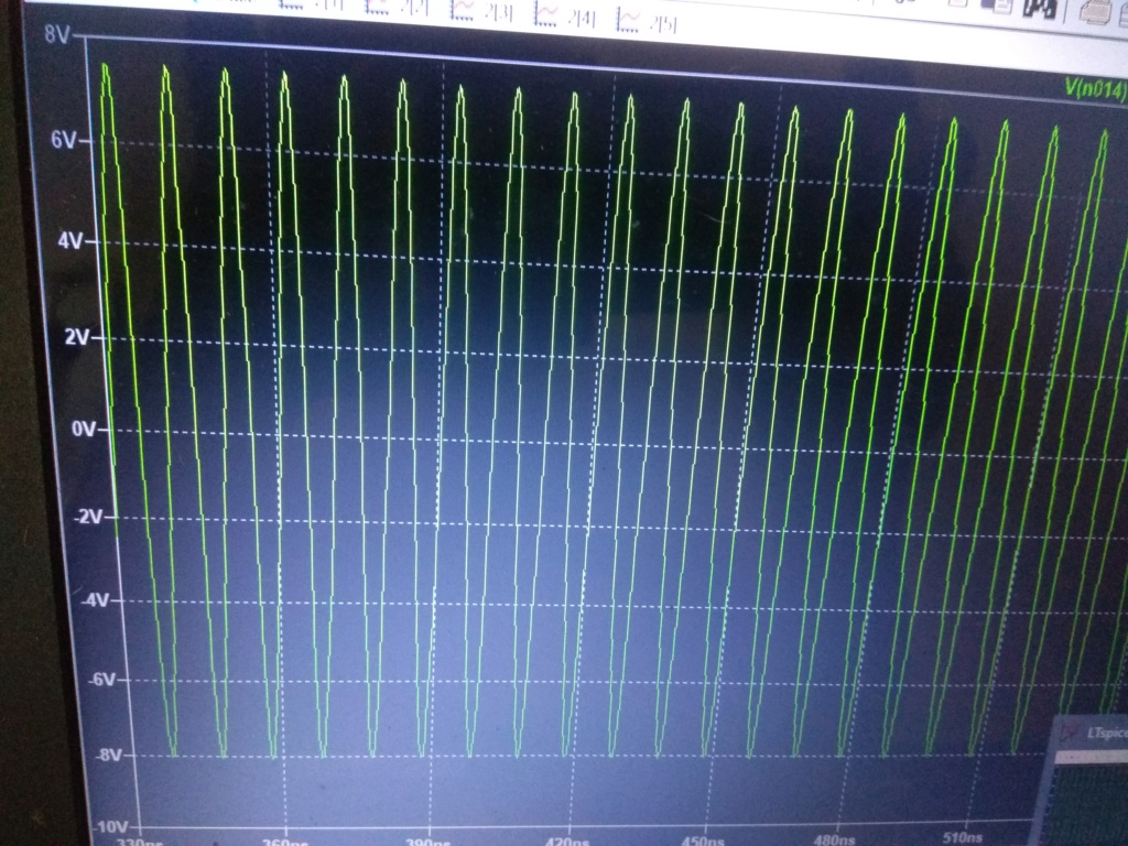
Yes, this schematic is tried and tested one. Make sure you order genuine plastic 2222A transistors. Power input was around 4mW and output was 550mW at 96MHz.
dare4444- Posts : 427
Join date : 2013-03-19
Re: Converting 500mW QRP amplifier to VHF amplifier
![]() by Suman Mon May 15, 2023 2:53 pm
by Suman Mon May 15, 2023 2:53 pm
I am glad to know that you can speak Bengali. It is my first language. Thank you for the information you provided to me. I have downloaded LTspice as you mentioned me to do. But it is new to me to operate. So, it will take time to get used to LTspice. Thanks for diagrams you attached with your last message. Hope it will be helpful to me and will give me food for thought. I have already collected your diagram which is given below

Your approch to use simple low power Transistors impresses me. That's why, you are my inspiration. Have a good time.
With thanks,
Suman
Suman- Posts : 8
Join date : 2022-08-11
Re: Suman
![]() by dare4444 Mon May 15, 2023 4:07 am
by dare4444 Mon May 15, 2023 4:07 am
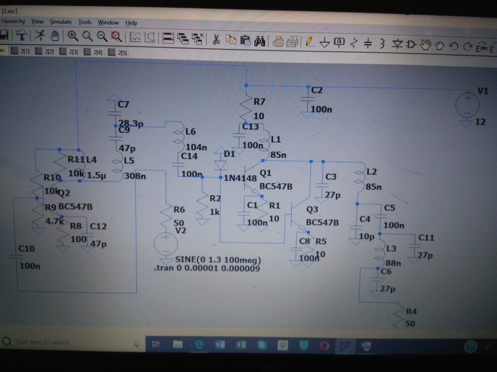
I speak Bengali as well. What's your WhatsApp? Please download LtSpice software. It's a great simulation tool and a complete RF amplifier can be build using just LtSpice. Check the attached pics. The two BC547 are used in parallel and the amplifier delivers half a watt when simulated on LtSpice. It's a very accurate tool for RF design.

dare4444- Posts : 427
Join date : 2013-03-19
Re: Converting 500mW QRP amplifier to VHF amplifier
![]() by Suman Sun May 14, 2023 9:32 pm
by Suman Sun May 14, 2023 9:32 pm
Hi Joy,
It's nice to get response from you. I followed you here and I saw some of your experimental circuits on FM transmitters and related RF amplifiers. I would like to let you know that I have become inspired by you. I have an interest on making vhf (FM) amplifiers by using simple small signal Transistors instead of RF power Transistors which are not available. I am from Bangladesh. I am really feeling thrilled to know about your 1W VHF amplifier which is the subject of my interest. Hoping for your reply. Have a wonderful time.
With thanks,
Suman
Suman- Posts : 8
Join date : 2022-08-11
Re:
![]() by dare4444 Sun May 14, 2023 5:03 am
by dare4444 Sun May 14, 2023 5:03 am

This circuit uses a PN2222A plastic transistor and delivers 250mW at 100MHz with 25mW of drive. The air core coils work without any hassle. Use a 100n DC blocking capacitor at its input. I used a plastic ballpen with an outer diameter of 8mm to wind the coils.
dare4444- Posts : 427
Join date : 2013-03-19
Suman likes this post
Re: Converting 500mW QRP amplifier to VHF amplifier
![]() by dare4444 Sat May 13, 2023 12:53 pm
by dare4444 Sat May 13, 2023 12:53 pm
Suman wrote:Hello Harry,
Thank you for your reply. I have attached 2 diagrams. Those are collected from Internet. 1st diagram is a class C push pull VHF amplifier, which produces 55W according to the description.
I am not going to do that. I just wish to follow the class C push pull concept for low power device in future .
2nd diagram is a low power FM transmitter from a Chinese website.
It consist of 44-54 Mhz VFO, a frequency doubler stage and a 3 Transistors amplifier stage. I have some low power C9018 Transistors to work with. It's transition frequency is around 1 Ghz but collector dissipation is very low (400mw maximum) I would like to let you know that I have built your 500mW HF Amp.
But I want to use it in FM (VHF) band after changing BC547 with C9018. The ft of C9018 is 10 times greater than my desired frequency (100Mhz).
So, it may be suitable for experiment and I will use vhf binocular balun core which I have collected from TV antenna booster.
I would love get advice to convert your 500mW QRP HF Amp to a VHF amp. Have a blessed day.
With thanks,
Suman.
Hello Suman,
Are you in India? I have an amplifier with 2N2222 transistors delivering 1W between 88-100 MHz and no heatsink needed! Final efficiency is 85% with two parallel 2N2222s. The circuit was developed as a replacement to the now obsolete 2N3866 transistor.
Joy
dare4444- Posts : 427
Join date : 2013-03-19
Suman likes this post
Re: Converting 500mW QRP amplifier to VHF amplifier
![]() by Suman Thu May 04, 2023 6:41 am
by Suman Thu May 04, 2023 6:41 am
Thank you for your reply. I have attached 2 diagrams. Those are collected from Internet. 1st diagram is a class C push pull VHF amplifier, which produces 55W according to the description.

I am not going to do that. I just wish to follow the class C push pull concept for low power device in future .
2nd diagram is a low power FM transmitter from a Chinese website.

It consist of 44-54 Mhz VFO, a frequency doubler stage and a 3 Transistors amplifier stage. I have some low power C9018 Transistors to work with. It's transition frequency is around 1 Ghz but collector dissipation is very low (400mw maximum) I would like to let you know that I have built your 500mW HF Amp.

But I want to use it in FM (VHF) band after changing BC547 with C9018. The ft of C9018 is 10 times greater than my desired frequency (100Mhz).

So, it may be suitable for experiment and I will use vhf binocular balun core which I have collected from TV antenna booster.

I would love get advice to convert your 500mW QRP HF Amp to a VHF amp. Have a blessed day.
With thanks,
Suman.
Suman- Posts : 8
Join date : 2022-08-11
Re: Converting 500mW QRP amplifier to VHF amplifier
![]() by Suman Thu May 04, 2023 5:14 am
by Suman Thu May 04, 2023 5:14 am
Ivan wrote:Hi Suman,Suman wrote:...The interesting fact is it's power Amp stage. It contains 3 Transistors, those are connected in parallel and also form a class C configuration. Multiple low power Transistors are in final stage to increase the output power. It's amp is divided into 2 part, 1st part is a 1 Transistor buffer amp and 2nd part is a 3 Transistors power amp.
With thanks,
Suman.
I have written this a while ago, but it disappeared someho! So once more:
Connecting bipolar transistors in parralel is possible and often used in PAs to achieve more power. Emitter resistors help to distribbute the current equally. The drawback is that parasitic capaitances add together.
Transistor V2 probably works as a frequency doubler, not a mere buffer. The coil in its collector has 4 times smaller inductance than the oscillator one, so with the same capacitor it resonates on twice the frequency.
VBR from Ivan
Hi Ivan,
Thank you for your observations on that Chinese circuit. You are absolutely right about v2. It is a frequency doubler. A low pass filter should be added with the output.
With thanks,
Suman
Suman- Posts : 8
Join date : 2022-08-11
Re: Converting 500mW QRP amplifier to VHF amplifier
![]() by Ivan Wed May 03, 2023 9:29 pm
by Ivan Wed May 03, 2023 9:29 pm
Hi Suman,Suman wrote:...The interesting fact is it's power Amp stage. It contains 3 Transistors, those are connected in parallel and also form a class C configuration. Multiple low power Transistors are in final stage to increase the output power. It's amp is divided into 2 part, 1st part is a 1 Transistor buffer amp and 2nd part is a 3 Transistors power amp.
With thanks,
Suman.
I have written this a while ago, but it disappeared somehow! So once more:
Connecting bipolar transistors in parralel is possible and often used in PAs to achieve more power. Emitter resistors help to distribute the current equally. The drawback is that parasitic capacitances add together.
Transistor V2 probably works as a frequency doubler, not a mere buffer. The coil in its collector has 4 times smaller inductance than the oscillator one, so with the same capacitor it resonates on twice the frequency.
VBR from Ivan
Last edited by Ivan on Thu May 04, 2023 6:50 am; edited 1 time in total
Ivan- Posts : 793
Join date : 2012-11-25
Age : 64
Location : Praha, Czechia
Suman likes this post
Re: Converting 500mW QRP amplifier to VHF amplifier
![]() by sm0vpo Wed May 03, 2023 9:13 pm
by sm0vpo Wed May 03, 2023 9:13 pm
This is an interesting circuit, but I would be very careful with it.
1 - It delivers a high RF power of 55 Watts
2 - It multiplies a 44MHz oscillator
I think that you should put this on a spectrum analyser before you connect an antenna.
If the fundamental oscillator frequency rejection is only about 50dB then you would have more than 0dBm of 44MHz radiation from the transmitter. Remember that 50dB is 1/100000 part reduction, and that may not be easy to achieve.
There is also a good chance that there is some 3rd harmonic in there at 132MHz (aircraft band). You are going to need some really good LPF and HPF filtering to get rid of any rubbish.
You may want to have a look at http://www.sm0vpo.com/info/pathloss_42.htm
BR Harry - sm0vpo
sm0vpo- Admin
- Posts : 110
Join date : 2013-03-26
Age : 72
Location : Märsta, Sweden
Re: Converting 500mW QRP amplifier to VHF amplifier
![]() by Ivan Wed May 03, 2023 9:00 pm
by Ivan Wed May 03, 2023 9:00 pm
the mix of ferrite is quite essential. A mix with low relative permeability has usually low losses at VHF. Types made for interference suppression and chokes have big permeability, higher losses and work best at hundreds of KHz.
"The usual method of aligning a filter is to use a spectrum analyser with a tracking-generator to sweep the band and watch the frequency response." Use of a spectrum analyzer and a wideband noise generarator is equally good.
I wish you being fit soon!
VBR from Ivan
Ivan- Posts : 793
Join date : 2012-11-25
Age : 64
Location : Praha, Czechia
Re: Converting 500mW QRP amplifier to VHF amplifier
![]() by Suman Wed May 03, 2023 8:28 pm
by Suman Wed May 03, 2023 8:28 pm
The schematic which I attached with my previous message is for 55W VHF amp. So Transistors are dedicated power Transistors. As usual, It's base & collector impedance would be low (actually unknown to me). If I replace those Transistors with a low power Transistor, then there is a chance to create a mismatch for the input and output Transformer's. So, it needs calculation & experiment to get perfection. I have found another circuit diagram from a Chinese website.
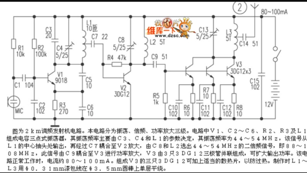
It's oscillator generates 44 Mhz to 54 Mhz. But at output, the frequency will be 88 Mhz to 108 Mhz after multiplying into double. The interesting fact is it's power Amp stage. It contains 3 Transistors, those are connected in parallel and also form a class C configuration. Multiple low power Transistors are in final stage to increase the output power. It's amp is divided into 2 part, 1st part is a 1 Transistor buffer amp and 2nd part is a 3 Transistors power amp.
With thanks,
Suman.
Suman- Posts : 8
Join date : 2022-08-11
Re: Converting 500mW QRP amplifier to VHF amplifier
![]() by sm0vpo Wed May 03, 2023 4:32 pm
by sm0vpo Wed May 03, 2023 4:32 pm
As you may be aware I ave been doing some recent work with ferrites at VHF.
At HF there is no problem, but I prefer too have formers with a closed magnetic field / ie. ferrite rings. This helps RF stability a lot since the magnetic containment also reduces radiation and pickup. I have made loads of amplifers that were in fact oscillators.
A few months ago I wrote a few articles that I see I have not yet updated to the homepages. There has been a lot of work using ferrites, and I may see about updating the homepages.
The ferrites I used for VHF are:
https://www.distrelec.biz/Web/Downloads/_t/ds/RND%20165-00182_eng_tds.pdf
You can see a project using them here:
http://sm0vpo.altervista.org/tx/fmtx_v8.htm
Sorry these pages are not on www.sm0vpo.com but the server has been recently updated and an older version of the homepages has been placed there. At the moment I am off work sick but I will try to make an effort to update the pages shortly.
The diagram you posted looks really simple. If you have the correct inductors then it should work very well, even for 100MHz. For 100MHz the BC547 and other such devices will work but may not give you the gain you sufficient gain.
BR Harry - sm0vpo
sm0vpo- Admin
- Posts : 110
Join date : 2013-03-26
Age : 72
Location : Märsta, Sweden
Suman likes this post
Re: Converting 500mW QRP amplifier to VHF amplifier
![]() by Ivan Wed May 03, 2023 4:09 pm
by Ivan Wed May 03, 2023 4:09 pm
it looks pretty simple and it may work, but its stability depends on the type of transistors. Class C is fine for FM, additional filtering of harmonics is required. My opinion is - give it a try!
VBR from Ivan
Ivan- Posts : 793
Join date : 2012-11-25
Age : 64
Location : Praha, Czechia
sm0vpo and Suman like this post
Re: Converting 500mW QRP amplifier to VHF amplifier
![]() by Suman Wed May 03, 2023 2:53 pm
by Suman Wed May 03, 2023 2:53 pm
Ivan wrote:Hi Suman,
the primary of Tr1 may be 1/2+1/2 turn perhaps. Or the Tr1 will be wound on a paramagnetic former instead of ferrite. The aim is to reduce the total inductance of the windings while keeping the impedance ratio.
Your English is O.K., I understand you perfectly. Do not worry.
VBR from Ivan
Hi lvan,
It's nice to get response from you. According to your suggestion, Transformer T1 can be air core or plastic former to reduce the inductance and to keep the impedance same. I have got another circuit diagram for VHF band in internet, that consist of 2 class C amp, which are connected in push pull arrangement.
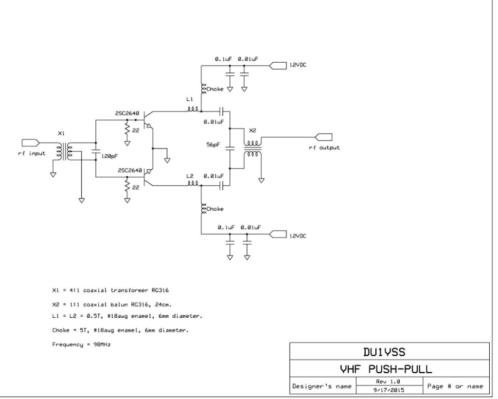
I have tried to include the diagram. I would request you to have a look. I am thinking of using low power Transistor instead of high power Transistor. What's on your mind?
With thanks
Suman.
Suman- Posts : 8
Join date : 2022-08-11
Re: Converting 500mW QRP amplifier to VHF amplifier
![]() by Ivan Tue May 02, 2023 6:48 pm
by Ivan Tue May 02, 2023 6:48 pm
the primary of Tr1 may be 1/2+1/2 turn perhaps. Or the Tr1 will be wound on a paramagnetic former instead of ferrite. The aim is to reduce the total inductance of the windings while keeping the impedance ratio.
Your English is O.K., I understand you perfectly. Do not worry.
VBR from Ivan
Ivan- Posts : 793
Join date : 2012-11-25
Age : 64
Location : Praha, Czechia
Suman likes this post
Re: Converting 500mW QRP amplifier to VHF amplifier
![]() by Suman Tue May 02, 2023 5:17 pm
by Suman Tue May 02, 2023 5:17 pm
Ivan wrote:Hi,
IMHO you will need less turns in both transformers for VHF. The resistors at T1 may be different to set the right DC operating point. Let us see what Harry tells.
VBR from Ivan OK1SIP
Hello Ivan,
Thank you for your reply. T1 transformer's impedance ratio will be changed if I reduce the primary winding. That may cause the mismatch It's primary contains 14turns and secondary have only 1+1 turns. So, there is no opportunity to reduce secondary winding to keep the impedance ratio unchanged. But T2 transformer's winding can be reduced. What I am saying can be wrong. In general, VHF Transformers contain few turns only. So you are right with that aspect. My English is not good. That's why, you may find difficulty to understand. Waiting for Harry to get the right path. Have a wonderful time.
With thanks
Suman
Suman- Posts : 8
Join date : 2022-08-11
Re: Converting 500mW QRP amplifier to VHF amplifier
![]() by Ivan Tue May 02, 2023 7:24 am
by Ivan Tue May 02, 2023 7:24 am
IMHO you will need less turns in both transformers for VHF. The resistors at T1 may be different to set the right DC operating point. Let us see what Harry tells.
VBR from Ivan OK1SIP
Ivan- Posts : 793
Join date : 2012-11-25
Age : 64
Location : Praha, Czechia
sm0vpo and Suman like this post
Converting 500mW QRP amplifier to VHF amplifier
![]() by Suman Mon May 01, 2023 10:27 pm
by Suman Mon May 01, 2023 10:27 pm
Greetings from my heart. I'm an electronics enthusiast. I have been following you for last 4 years or more. I would like to let you know that I have built your 500mW HF AMP by using 5 pieces of BC547 Transistor. But I want to use the same circuit as an amp in commercial FM band. I will replace the BC547 with C9018. Because the transition frequency of C9018 is around 1Ghz, so it is 10 times greater than my desired frequency (100Mhz). I have collected 2 balun cores for the RF transformer from an old TV antenna booster. Would it be possible to build that amp for VHF band without changing the other parts? If not then what to do for that. Hope I won't be disappointed. I am waiting to get your advice.
With thanks
Suman
Last edited by Suman on Thu May 04, 2023 7:01 am; edited 1 time in total
Suman- Posts : 8
Join date : 2022-08-11
sm0vpo likes this post
» Converting a class C FM PA to AB or AB1 'linear'
» 4W AF Amplifier
» 400 mw VHF amplifier
» AF amplifier idea
|
|
|