New project (start) on www.sm0vpo.com - CMOS timebase for oscilloscope


Prototype works fine - more to come
![]() by admin Thu Mar 26, 2020 7:16 pm
by admin Thu Mar 26, 2020 7:16 pm
Just a little update. I am in Spain, same situation, but before I came here I built the prototype. Worked perfectly 

Prototype waveform. Three micro-glitches at 25%, 50% and 75% at the fastest range (almost 100kHz)
Top range limited because of cable capacitance for the timing cap.
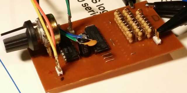
I used Arduina wires with the plugs ready fitted.
Green/blue is the timing cap.
Orange/yellow id the 12V power
8-bit D-A used 4K7 resistors.
Final version:
1 - 9-bit D-A for all but the fastest range, using 22K resistors
2 - Interface board will be a 7-bit D-A using 4K7
3 - Fewer links - board laid out a little differently
4 - I/F board will have a breakout for INH and RST for the trigger board
Just spent a few hours tidying it all up after corrections from prototype.
BR Harry - SM0VPO
(Still in Spain. Torrential rain. Corona lock-down. Hope to be home on Saturday on an emergency SAS flight. Only cost SEK11,000)
Prototype waveform. Three micro-glitches at 25%, 50% and 75% at the fastest range (almost 100kHz)
Top range limited because of cable capacitance for the timing cap.
I used Arduina wires with the plugs ready fitted.
Green/blue is the timing cap.
Orange/yellow id the 12V power
8-bit D-A used 4K7 resistors.
Final version:
1 - 9-bit D-A for all but the fastest range, using 22K resistors
2 - Interface board will be a 7-bit D-A using 4K7
3 - Fewer links - board laid out a little differently
4 - I/F board will have a breakout for INH and RST for the trigger board
Just spent a few hours tidying it all up after corrections from prototype.
BR Harry - SM0VPO
(Still in Spain. Torrential rain. Corona lock-down. Hope to be home on Saturday on an emergency SAS flight. Only cost SEK11,000)
_________________
Everything in this world is either bacon, or it isn't bacon
They say that money cannot bring you happiness, but if you have it then you can always buy more bacon

admin- Admin
- Posts : 1144
Join date : 2012-11-24
Age : 72
Location : Märsta, Sweden -

New project (start) on www.sm0vpo.com - CMOS timebase for oscilloscope
![]() by admin Sun Nov 24, 2019 11:42 pm
by admin Sun Nov 24, 2019 11:42 pm
Hi all,
I am stuck in Spain, with no rig, no workshop - nada!
When they say "the rain in Spain falls mainly in the plain" don't you believe it. We have had three days of non-stop rain. Almost expecting the coming of another Noa. So I have spent a few hours (a lot of hours) on a new project, loosely based on an old project. Same circuit (almost) but put to a different use.
I have been planning an update to my oscilloscope project. The tube drivers (ECC81/12AT7) and the 1200 Volt PSU I am 100% happy with, but an oscilloscope needs a good sweep circuitry and a good trigger. Unfortunately I need an oscilloscope to develop this!!
Anyway, the tube/transistor scope is (sort of) working, back in Sweden, but I am not at all happy with it. Instead of just planning loads of stuff I have decided to make the homepages my lab-book, and document my thoughts. I have also created a PCB drawing. You can find the project at theis link:
http://sm0vpo.altervista.org/scope/oscilloscope-timebase-digital.htm
It is ridiculously simple, but there are some important points to consider. If you can read them and give me any comments, suggestions or ideas then I would be really grateful. If you think it will fly, then please say so. Please post any technical comments or suggestions to the questions/technical board (and not this homepage news board).
Very best regards from Harry - EA/SM0VPO (rig-less)
(PS - I do have ECHOLINK and I have had a few contacts on it during the last couple of weeks.)
_________________
Everything in this world is either bacon, or it isn't bacon
They say that money cannot bring you happiness, but if you have it then you can always buy more bacon
admin- Admin
- Posts : 1144
Join date : 2012-11-24
Age : 72
Location : Märsta, Sweden -
» New project on www.sm0vpo.com - Basic HF / VHF filters
» New project on HHH http://sm0vpo.altervista.org/ (www.sm0vpo.com later)
» New project on www.sm0vpo.com - 3D Printed Portable HF Antenna
» Yet another new project on www.sm0vpo.com
» New project on www.sm0vpo.com - For IVAN
» New project on HHH http://sm0vpo.altervista.org/ (www.sm0vpo.com later)
» New project on www.sm0vpo.com - 3D Printed Portable HF Antenna
» Yet another new project on www.sm0vpo.com
» New project on www.sm0vpo.com - For IVAN
Permissions in this forum:
You can reply to topics in this forum