High Power XTAL FM Mic
2 posters
Page 1 of 1
 Re: High Power XTAL FM Mic
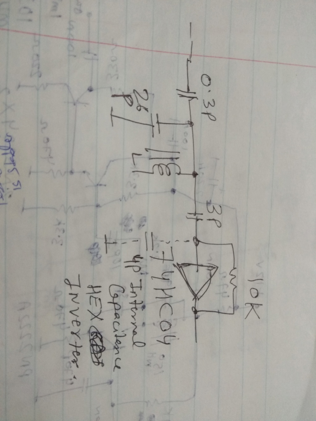
Hi,dare4444 wrote:The HEX inverter has 4pf input capacitance.
If we add 3p BPF coupling cap and the internal 4p.. = 7p
26p is the resonator cap.
thei input capacitance is in series with the coupling cap
(4x3)/(4+3)= 1,7 pF
It is less than 10% tolerance of the resonator capacitor.
The theory around LC filters is more complicated than that of a single resonant circuit. If there are any doubts, try to check the circuit with a spectrum analyzer.
BR from Ivan
Ivan- Posts : 793
Join date : 2012-11-25
Age : 64
Location : Praha, Czechia
 Re: High Power XTAL FM Mic
Ok I still don't understand this strange behavior. The second coil has to be 65-75nH for 74HC04 to lock onto 100MHz. I did test the range and its solid so 100MHz is the main output frequency.
The HEX inverter has 4pf input capacitance.
If we add 3p BPF coupling cap and the internal 4p.. = 7p
26p is the resonator cap.
26+7 = 33p
33p and 76nH resonates on 100.5MHz
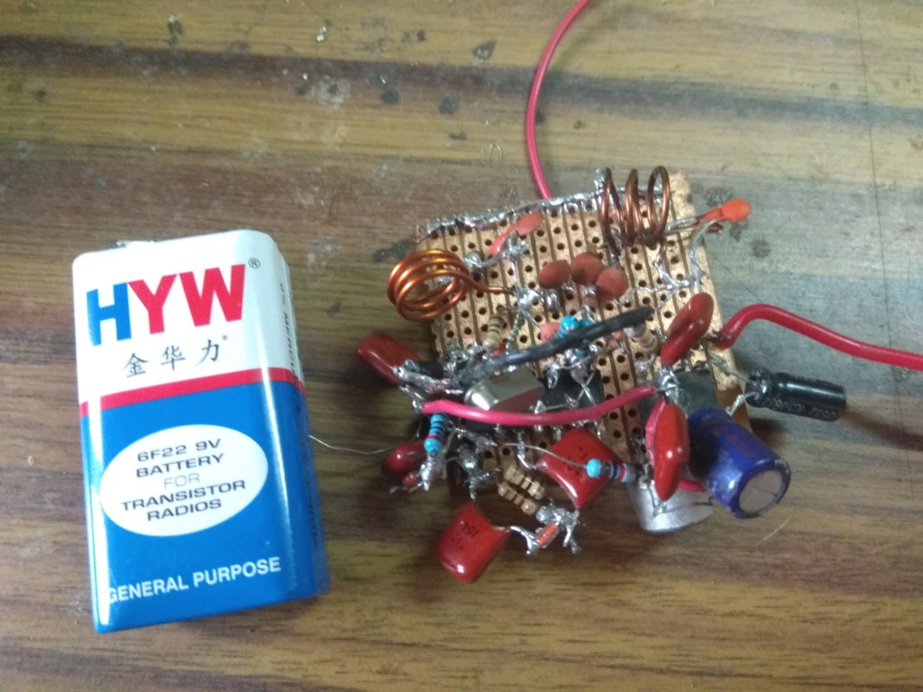
Is this what's going on? You can see the second BPF coil is stretched in the prototype picture to bring the inductance down to 75nH or so and then the HEX inverter gives 100MHz out and stays locked to the fifth harmonic of the crystal.
Ivan, Harry, can anyone help?

Last edited by dare4444 on Thu Jun 04, 2020 7:07 pm; edited 2 times in total
dare4444- Posts : 427
Join date : 2013-03-19
 High Power XTAL FM Mic
Adjust coil L2 very carefully for 100MHz lock on a frequency counter. It should lock on to 100MHz everytime the circuit is turned on. If not, then make minor changes to L2 by lightly compressing or expanding the coil until fast lock is achieved upon powering up. The mic is so sensitive, thanks to an AF gain of 200 (LM386), it picked up my voice from across the living room. Audio is loud and crisp thanks to the excellent varicap properties of IN4007. If there's reverse leakage and IN4007 draws more current resulting in a voltage drop, then the 56K resistor can be replaced with a high value molded inductor or RFC. Any value between 22uH and 1mH will do. Supply voltage to the IC is regulated to about 5.6V so a drop in battery voltage shouldn't be a concern till it gets down to 7V or so and then it might start to affect the modulation. This wireless mic should work fine with 7 to 9V of V+ input. A 9V (8.4V when fully charged) rechargable battery can be used here. Six rechargeable AAA cells will considerable increase operating time.
If you wish to transmit music then remove the microphone and 8.2K biasing resistor,feed line level audio directly to pin 3 of LM386 via a 100n series capacitor. The circuit can be powered with a 12V power supply as well. The 2n3904 regulator is barely warm and doing its job well by keeping positive supply to 74HC04 well below its 6V limit.
Any ideas on how to reduce input current even further? LM386 draws 4ma quiescent current, gives high gain with good audio quality, and external parts count is reduced. It seemed to be the perfect choice.
For different frequencies, use different crystals. This TX transmits on 5th harmonic but the 7th harmonic could be used as well, and using 74AC04 version of the chip will easily cover the 2m ham band in case any hams out there wish to try this circuit.
For domestic FM band, a18MHz crystal will give 90MHz (5X) output.
BPF values for different TX frequency can be calculated here https://www.changpuak.ch/electronics/Direct-Coupled-Resonator-Bandpass.php
Use 73cm wire antenna for 100MHz. Output impedance of this TX is 50ohm. With a 50ohm resistor connected as dummy load, RF peak voltage reading on my diode probe was 0.6V
0.6V + 0.5V diode loss = 1.1
Po = 1.1 x 1.1 / 50 x 2
= 11mW
The other two remaining inverters can be connected in parallel and driven with N4 and output taken from N5 and N6 and this TX will deliver 30mW but current consumption will increase accordingly to 53ma.
I am very satisfied by the performance of this circuit and its range. Audio quality is very good. The two 18p feedback capacitors on N1 can be increased to 27p for slightly better audio quality or they can be replaced with two IN4007 diodes and both diodes modulated with two series resistors. For now, just increasing 18p to 27p will improve audio quality.


Last edited by dare4444 on Sun Jun 14, 2020 6:29 am; edited 5 times in total
dare4444- Posts : 427
Join date : 2013-03-19
 Similar topics
» tunable Xtal oscillator circuit
» High Quality 16 bit AM PWM Arduino TX
» Mains power fluctuations
» Hi Power FM mic V5
» INFO (not question) High Quality from street market
» High Quality 16 bit AM PWM Arduino TX
» Mains power fluctuations
» Hi Power FM mic V5
» INFO (not question) High Quality from street market
Page 1 of 1
Permissions in this forum:
You can reply to topics in this forum|
|
|


