High Quality 16 bit AM PWM Arduino TX


Page 1 of 2 • 1, 2 ![]()

Re: High Quality 16 bit AM PWM Arduino TX
![]() by Ivan Sat Feb 12, 2022 7:26 am
by Ivan Sat Feb 12, 2022 7:26 am
Yes, in a system that can represent a word in a single memory cell or register. It may be a 16, 32 or 64 bit based system. 8 bit based systems can represent a word as two separate bytes only, otherwise an overflow and data loss result.dare4444 wrote:High byte * 256 + Low byte = single word. An example.
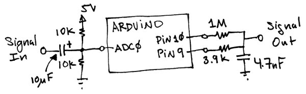
"Low byte / 256 + High Byte - This is what those two resistors are doing, attenuating low byte then adding to high byte."
They do that in the voltage domain. The result is an analog voltage. Analog computers used to work exactly that way. You would need another ADC to get back to the digital domain...
"We could do it digitally it seems so. This way we have 10 bit audio but more PWM steps to lower noise."
Unmistakably. We need a system, which can represent, store and process at least 10 bits in a single register. It will be a 16 bit based MCU in practice. It should have an ADC with 16 bit resolution, 16 bit wide registers and a PWM generator driven by 16 bits. It will do the job perfectly.
Your problem is you are mixing three different domains: an analog voltage domain, a timing domain of PWM and a digital domain with its bit/byte/word representation. Transition among them is not-so-easy. Try to think in these cathegories.
My proposal to generate the PWM by a voltage controlled circuit without digitizing did not catch your interest? A generator of triangles would replace the up-down counter, an analog comparator would produce PWM with timing resolution limited by noise only. No MCU would be required.
VBR from Ivan
Ivan- Posts : 793
Join date : 2012-11-25
Age : 64
Location : Praha, Czechia
Ruud likes this post
Re: High Quality 16 bit AM PWM Arduino TX
![]() by dare4444 Sat Feb 12, 2022 2:38 am
by dare4444 Sat Feb 12, 2022 2:38 am
High byte * 256 + Low byte = single word. An example.
Low byte / 256 + High Byte - This is what those two resistors are doing, attenuating low byte then adding to high byte. We could do it digitally it seems so. This way we have 10 bit audio but more PWM steps to lower noise.
dare4444- Posts : 427
Join date : 2013-03-19
Re: High Quality 16 bit AM PWM Arduino TX
![]() by Ivan Thu Feb 10, 2022 6:49 pm
by Ivan Thu Feb 10, 2022 6:49 pm
I am not a fan of SDR. A few people are able to write the program for a SW defined receiver or TRX from scratch and understand fully what it does. Making SDR seems boring to me at the same time. To download a code I do not fully understand, buy a set of complex chips I do not know what they do and put it together is not my cup of tea.
VBR from Ivan
Ivan- Posts : 793
Join date : 2012-11-25
Age : 64
Location : Praha, Czechia
Re: High Quality 16 bit AM PWM Arduino TX
![]() by dare4444 Thu Feb 10, 2022 4:16 pm
by dare4444 Thu Feb 10, 2022 4:16 pm
It's a powerful chip, same price as arduino. Now hams are gonna build all kind of stuff with it utilizing its power. Google uSDX transceiver. Arduino is both receiving and synthesizing SSB!!! Now a quick practical ssb txr could be built for 20 bucks. Imagine the potential of pico pi then. It will phase out Arduino.
dare4444- Posts : 427
Join date : 2013-03-19
Re: High Quality 16 bit AM PWM Arduino TX
![]() by dare4444 Thu Feb 10, 2022 1:18 pm
by dare4444 Thu Feb 10, 2022 1:18 pm
Reply vanished. Will reply againIvan wrote:Is the Mega 16 bit based? I have never used it in my project. Does it have a 16 bit ADC and a 16 bit driven PWM generator? If it is not the case, I am afraid it will not help you.dare4444 wrote:I ordered Arduino mega for $15. Wrote this code all night. After brain storming.
You should really take a pause, mainly with the respect to your illness.
VBR Ivan
dare4444- Posts : 427
Join date : 2013-03-19
Re: High Quality 16 bit AM PWM Arduino TX
![]() by Ivan Thu Feb 10, 2022 7:11 am
by Ivan Thu Feb 10, 2022 7:11 am
Is the Mega 16 bit based? I have never used it in my project. Does it have a 16 bit ADC and a 16 bit driven PWM generator? If it is not the case, I am afraid it will not help you.dare4444 wrote:I ordered Arduino mega for $15. Wrote this code all night. After brain storming.
You should really take a pause, mainly with the respect to your illness.
VBR Ivan
Ivan- Posts : 793
Join date : 2012-11-25
Age : 64
Location : Praha, Czechia
Re: High Quality 16 bit AM PWM Arduino TX
![]() by Ivan Thu Feb 10, 2022 7:05 am
by Ivan Thu Feb 10, 2022 7:05 am
It would achieve a total mess.dare4444 wrote:What would combining in the gate achieve? Same resolution I guess.
VBR Ivan
Ivan- Posts : 793
Join date : 2012-11-25
Age : 64
Location : Praha, Czechia
Re: High Quality 16 bit AM PWM Arduino TX
![]() by Ivan Thu Feb 10, 2022 7:00 am
by Ivan Thu Feb 10, 2022 7:00 am
Yes. The output is an analog image of the analog signal on the ADC input plus sampling and quantization noise. What do you want to do with this analog signal? You can feed it into an analog modulator. Processing it with logic circuits will not work.dare4444 wrote:Resistor divider is supplied with two pins, both could be
00,01,10,11 , between 5V or 3.3 (Arduino?) And gnd. Resistor divider would divide the voltage, that's its job! Lol. With the capacitor the output must look like a staircase with many many tiny steps.
What is you want to get is a series of pulses between H and L, i.e. of the same height, lasting of which differs in little steps.
I remember a very old project, in which I generated PWM for an optical link using a multivibrator, controlled by a varicap. No MCU, no ADC, no coils were used; a varicap, several NAND gates, some resistors and capacitors did the job. I fed the input signal into the varicap and it worked! The leading edges of pulses copied the clock, the trailing edges moved according to the momentary value of the input voltage (averaged during one pulse). To be correct, a sample and hold circuit should be added, so that the voltage on the varicap did not change during the pulse, but the circuit worked satisfactorily even without it. What about using your Arduino Nano as a source of sampling clock and carrier only, generating the PWM in such hardwired circuit?
VBR Ivan
Ivan- Posts : 793
Join date : 2012-11-25
Age : 64
Location : Praha, Czechia
Re: High Quality 16 bit AM PWM Arduino TX
![]() by dare4444 Thu Feb 10, 2022 4:55 am
by dare4444 Thu Feb 10, 2022 4:55 am
#define WGM1_MODE 0b1000 // fast (14) or phase correct (
#define PWM_MODE 0 // Fast (1) or Phase Correct (0) WGM 14 or 8, TOP = ICR
#define PWM_QTY 2 // number of pwms are 2
void setup() {
//Set up pin 6 for 1600KHz carrier out with 50% duty cycle
pinMode(5, OUTPUT);
pinMode(6, OUTPUT);
TCCR0A = 0; //reset the A register for timer0
TCCR0B = 0; //reset the B register for timer0
TCCR0A = 0b01010011; // fast pwm mode on pin 5 & 6
TCCR0B = 0b00001001; // no prescaler and WGM02 is 1
OCR0A = 9; //control value, sets frequency to 1600KHz or 16MHz / (OCR0A+1)
//Carrier has been set
// setup ADC Analog Input Pin A0
ADMUX = 0x60; // left adjust, selects A0 as adc input pin, internal vcc
ADCSRA = 0xe4; // turn on adc, sets prescaler to 16MHz clock / 16 = 1MHz ADC speed in free running mode, auto trigger
ADCSRB = 0x07; // t1 capture for trigger
DIDR0 = 0x01; // turn off digital inputs for adc0 or pin A0
// setup PWM
//TCCR1A = (((PWM_QTY - 1) << 5) 0x80 (PWM_MODE << 1)); //
//TCCR1B = ((PWM_MODE << 3) 0x11); // ck/1, clock = 1MHz
TCCR1A = (0b10 << COM1A0) | (0b10 << COM1B0) | ((WGM1_MODE & 0b11) << WGM10); // OC1A, QC1B
#ifdef COM1C0
// Mega, Leonardo
TCCR1A |= (0b10 << COM1C0); // OC1C
pinMode(13, OUTPUT); // OC0A & OC1C
#endif
TCCR1B = (WGM1_MODE >> 2) << WGM12 | (0b001 << CS10); // /1 prescaler
// PWM_MODE1 -> WGM 1110 or 0: 1000
TIMSK1 = 0x20; // interrupt on capture interrupt
ICR1H = (PWM_FREQ >>
ICR1L = (PWM_FREQ & 0xff); // pwm frequency set, total bit 16, pwm freq = 1MHz/16 bit = 62.5KHz for 16 bit, 31.25KHz for each 8 bit on D9 & D10. The PWM bits are combined with the 1600KHz carrier frequency in CD4012, a 4 input nand gate, when input 1111 output = 0, second gate inverts it to logic 1 , when input 1111 output of CD4012 = 1
// DDRB = ((PWM_QTY << 1) 0x02); // turn on outputs
sei(); // turn on interrupts - not really necessary with arduino
}
void loop() {
while (1); // gets rid of jitter for smooth pwm
}
ISR(TIMER1_CAPT_vect) {
// get ADC data
unsigned int temp1 = ADCL; // fetch low byte first
unsigned int temp2 = ADCH; // fetch high byte
// ADCH and ADCL 8 bits each are represented
// output high byte on OC1A
OCR1AH = temp2 >> 8; // takes top 8 bits
OCR1AL = temp2; // takes bottom 8 bits
// output low byte on OC1B
OCR1BH = temp1 >> 8;
OCR1BL = temp1;
#ifdef OC1C
// Use OCM1C0A modulation on OC1C and OC0A pin, #13
OCR1C = ADC >> 2 ; // just top 8 bits of 10 bit ADC
#endif
/* top 8 and bottom 8 audio bits as 31.25KHz PWM square waves are
combined together in four input nand gate CD4012 along with the
1600KHz carrier frequency from D6. Sampling frequency is 64KHz for
high fidelity audio. The second nand gate inverts the output signal
to positive or logic 1 and drives a totem pole output stage for low
impedance output. Add a 5 pole low pass filter to remove the harmonics
before transmitting. Arduino is a $4 Nano version.
(Or a Mega or Leonardo for trying OCM1C0A on the OC1C/OC0A pin)
*/
}
I ordered Arduino mega for $15. Wrote this code all night. After brain storming.
dare4444- Posts : 427
Join date : 2013-03-19
Re: High Quality 16 bit AM PWM Arduino TX
![]() by dare4444 Wed Feb 09, 2022 10:52 pm
by dare4444 Wed Feb 09, 2022 10:52 pm
dare4444- Posts : 427
Join date : 2013-03-19
Re: High Quality 16 bit AM PWM Arduino TX
![]() by dare4444 Wed Feb 09, 2022 10:30 pm
by dare4444 Wed Feb 09, 2022 10:30 pm
I'm taking it for 2 years, codeine upto 600mg a day with acetaminophen. I've myofascial pain syndrome and even typing on phone for hours triggers it. But i am on phone for hours on end, learning new stuff, obsession with circuits. Today I took less, surprising how my mind cleared it! If I stay active, no phone Or laptop or homebrewing, then meds need vanishes. Dealing with chronic pain since 2004.Ivan wrote:Sorry for your health issue. I was given opioids when I was in a hospital three years ago - with my back. They made the pain acceptable, but reduced my conciousness. I use weaker medication now.dare4444 wrote:Back problems. Pain meds took away by critical thinking ability. It's weird, gonna taper and stop. It's opiate based.
If one pwm is scaled down to 0-255mV in 1mV step, then summing two pwms of equal amplitude should double resolution to 510mV, am I right? It's 1 bit extra, 9 bit resolution.
The PWM has always two voltage levels only, L and H (0V and 3,3/5V). It is a logic, digital signal. The information is encoded in the timing of the pulses. There are no voltage steps in PWM! No voltage scaling is possible! Sorry, you are not right at all.
The only exception is converting PWM to analog signal by setting the H level in a resistor network and integrating it by a capacitor. This method is not 100% correct, it introduces specific distortion, but it works somehow. (The correct method is rather similar to demodulation of frequecy or phase modulation.) The result is an analog signal, which cannot be further processed in logic circuits.
No, it is not the proper way.
VBR Ivan
Due to opiates I hit mental block. Resistor
divider is supplied with two pins, both could be
00,01,10,11 , between 5V or 3.3 (Arduino?) And gnd. Resistor divider would divide the voltage, that's its job! Lol. With the capacitor the output must look like a staircase with many many tiny steps.
dare4444- Posts : 427
Join date : 2013-03-19
Re: High Quality 16 bit AM PWM Arduino TX
![]() by Ivan Wed Feb 09, 2022 8:11 pm
by Ivan Wed Feb 09, 2022 8:11 pm
Sorry for your health issue. I was given opioids when I was in a hospital three years ago - with my back. They made the pain acceptable, but reduced my conciousness. I use weaker medication now.dare4444 wrote:Back problems. Pain meds took away by critical thinking ability. It's weird, gonna taper and stop. It's opiate based.
If one pwm is scaled down to 0-255mV in 1mV step, then summing two pwms of equal amplitude should double resolution to 510mV, am I right? It's 1 bit extra, 9 bit resolution.
The PWM has always two voltage levels only, L and H (0V and 3,3/5V). It is a logic, digital signal. The information is encoded in the timing of the pulses. There are no voltage steps in PWM! No voltage scaling is possible! Sorry, you are not right at all.
The only exception is converting PWM to analog signal by setting the H level in a resistor network and integrating it by a capacitor. This method is not 100% correct, it introduces specific distortion, but it works somehow. (The correct method is rather similar to demodulation of frequecy or phase modulation.) The result is an analog signal, which cannot be further processed in logic circuits.
No, it is not the proper way.
VBR Ivan
Ivan- Posts : 793
Join date : 2012-11-25
Age : 64
Location : Praha, Czechia
dare4444 likes this post
Re: High Quality 16 bit AM PWM Arduino TX
![]() by dare4444 Wed Feb 09, 2022 11:54 am
by dare4444 Wed Feb 09, 2022 11:54 am
Back problems. Pain meds took away by critical thinking ability. It's weird, gonna taper and stop. It's opiate based.Ivan wrote:Sorry, you are lost totally. Using an RC combiner/integrator would return you back to the analog voltage domain. The gate would work as a mere comparator, giving a H or L level for each sample. The resulting resolution would be ... 1 bit.dare4444 wrote:The resistor combiner divides d low byte by 256 to add low voltage steps in the ladder for increased resolution. Combining it with gate, may be one more bit of resolution would be added max as two values got same voltage stepsI have already written here, you could omit the Arduino and load the AF directly to the gate and you would obtain the same crap.
You are mentally running in a circle full of mistakes. Take a pause and then restart the project from scratch.
VBR Ivan
The 1M resistor attenuates the lower byte output by 256. We are then adding it with the first byte.
If one pwm is scaled down to 0-255mV in 1mV step, then summing two pwms of equal amplitude should double resolution to 510mV, am I right? It's 1 bit extra, 9 bit resolution.
Now if we use 1:32 ratio, then other bit would would be adding 256/32 = 8mV on top the analogue voltage.
3.9k : 1M adds 1mV only (256/256)
Do I get it now?
dare4444- Posts : 427
Join date : 2013-03-19
Re: High Quality 16 bit AM PWM Arduino TX
![]() by Ivan Wed Feb 09, 2022 9:18 am
by Ivan Wed Feb 09, 2022 9:18 am
Sorry, you are lost totally. Using an RC combiner/integrator would return you back to the analog voltage domain. The gate would work as a mere comparator, giving a H or L level for each sample. The resulting resolution would be ... 1 bit.dare4444 wrote:The resistor combiner divides d low byte by 256 to add low voltage steps in the ladder for increased resolution. Combining it with gate, may be one more bit of resolution would be added max as two values got same voltage steps
You are mentally running in a circle full of mistakes. Take a pause and then restart the project from scratch.
VBR Ivan
Ivan- Posts : 793
Join date : 2012-11-25
Age : 64
Location : Praha, Czechia
Ruud likes this post
Re: High Quality 16 bit AM PWM Arduino TX
![]() by dare4444 Wed Feb 09, 2022 8:47 am
by dare4444 Wed Feb 09, 2022 8:47 am
Yes I got it.Ivan wrote:No. We need a counter, which will - after the ADC takes one sample - compare 256 times with the MSB and then with the LSB once. A new sample will be taken after that. The average of 257 width modulated pulses will represent the value of each sample with 16 bit resolution. The CLK of the PWM counter is limiting, as we need 256x257= 65792 counter steps up and 65792 steps down per each sample.dare4444 wrote:We need a digital counter at the output switching between high byte and low byte pulses every 255 cycle? Clk is 1MHz for ADC and each conversion takes 13.5 cycle. Surprisingly there is no 256 value in phase correct mode. 0-255 , 255-0 and timer toggles off and on in sync with the decimal value of audio input.
And we need a true 16 bit ADC to feed the PWM generator with 16 bit (one word) data.
"I have hit a mental block. This is my first time with pwm in Arduino."
Try to reset your brain. Abandon this project and Arduino for several days and do something else.
VBR Ivan
The resistor combiner divides d low byte by 256 to add low voltage steps in the ladder for increased resolution. Combining it with gate, may be one more bit of resolution would be added max as two values got same voltage steps
dare4444- Posts : 427
Join date : 2013-03-19
Re: High Quality 16 bit AM PWM Arduino TX
![]() by Ivan Wed Feb 09, 2022 6:55 am
by Ivan Wed Feb 09, 2022 6:55 am
No. We need a counter, which will - after the ADC takes one sample - compare 256 times with the MSB and then with the LSB once. A new sample will be taken after that. The average of 257 width modulated pulses will represent the value of each sample with 16 bit resolution. The CLK of the PWM counter is limiting, as we need 256x257= 65792 counter steps up and 65792 steps down per each sample.dare4444 wrote:We need a digital counter at the output switching between high byte and low byte pulses every 255 cycle? Clk is 1MHz for ADC and each conversion takes 13.5 cycle. Surprisingly there is no 256 value in phase correct mode. 0-255 , 255-0 and timer toggles off and on in sync with the decimal value of audio input.
And we need a true 16 bit ADC to feed the PWM generator with 16 bit (one word) data.
"I have hit a mental block. This is my first time with pwm in Arduino."
Try to reset your brain. Abandon this project and Arduino for several days and do something else.
VBR Ivan
Ivan- Posts : 793
Join date : 2012-11-25
Age : 64
Location : Praha, Czechia
Ruud likes this post
Re: High Quality 16 bit AM PWM Arduino TX
![]() by Ivan Wed Feb 09, 2022 6:31 am
by Ivan Wed Feb 09, 2022 6:31 am
Bit or byte according to the context. Here I use it for BYTE. In some cases MSb, LSb is used for bit and MSB, LSB for byte.
"The program is a standard code. I edited and added/deleted many lines of code to suit my application."
Often it is better to write your own code from scratch, using examples for inspiration only.
VBR Ivan
Ivan- Posts : 793
Join date : 2012-11-25
Age : 64
Location : Praha, Czechia
Re: High Quality 16 bit AM PWM Arduino TX
![]() by dare4444 Tue Feb 08, 2022 11:25 pm
by dare4444 Tue Feb 08, 2022 11:25 pm
dare4444- Posts : 427
Join date : 2013-03-19
Re: High Quality 16 bit AM PWM Arduino TX
![]() by dare4444 Tue Feb 08, 2022 11:23 pm
by dare4444 Tue Feb 08, 2022 11:23 pm
Ivan wrote:VBR Ivandare4444 wrote:Each output starts with most significant bit and least significant bit and spits out the binary byte one after other, like 8 bit + 8 bit?
It depends on the program of the MCU. You wrote it, so you know better what it does. I suppose each output sends out PWM pulses driven by a binary value, not bits themselves. Of course serial output can be programmed, too.
In software there's a function called union. High and low byte are combined in a single integer. Is it gonna be of any use?
Probably not. That "single integer" is the ADC output, you want to split it to two bytes as Arduinos do not have 16 bit wide register for PWM.
I know that two 8 bit binary numbers can be subtracted for one 8 bit output.
Yes, any arithmetics can be performed with binary numbers, as well as bitwise logic operations (it is not the same!) and Boolean operations. It is of no use in this case.
Could you explain more about this highbyte and lowbyte ?
Ehhh... it is the basics... what more to say? The ADC gives us 10 bits, i.e. 000000nn:nnnnnnnn binary. We can represent it as one word 16 bits long, or two bytes of 8 bits each. The high one (MSB) is the left one and it has 256 times more weight than the low one (LSB).
Yes. Most and least significant bit, I know. I'm not much familiar with the internal working of atmega328. You're right. Each output sends out pulses of varying width as the timer encounters ADC data and turns on and off.
https://www.basic4mcu.com/bbs/board.php?bo_table=h14&wr_id=209&device=mobile
Atmega, how PWM works.
The program is a standard code. I edited and added/deleted many lines of code to suit my application.
dare4444- Posts : 427
Join date : 2013-03-19
Re: High Quality 16 bit AM PWM Arduino TX
![]() by Ivan Tue Feb 08, 2022 11:13 pm
by Ivan Tue Feb 08, 2022 11:13 pm
VBR Ivandare4444 wrote:Each output starts with most significant bit and least significant bit and spits out the binary byte one after other, like 8 bit + 8 bit?
It depends on the program of the MCU. You wrote it, so you know better what it does. I suppose each output sends out PWM pulses driven by a binary value, not bits themselves. Of course serial output can be programmed, too.
In software there's a function called union. High and low byte are combined in a single integer. Is it gonna be of any use?
Probably not. That "single integer" is the ADC output, you want to split it to two bytes as Arduinos do not have 16 bit wide register for PWM.
I know that two 8 bit binary numbers can be subtracted for one 8 bit output.
Yes, any arithmetics can be performed with binary numbers, as well as bitwise logic operations (it is not the same!) and Boolean operations. It is of no use in this case.
Could you explain more about this highbyte and lowbyte ?
Ehhh... it is the basics... what more to say? The ADC gives us 10 bits, i.e. 000000nn:nnnnnnnn binary. We can represent it as one word 16 bits long, or two bytes of 8 bits each. The high one (MSB) is the left one and it has 256 times more weight than the low one (LSB).
Ivan- Posts : 793
Join date : 2012-11-25
Age : 64
Location : Praha, Czechia
Re: High Quality 16 bit AM PWM Arduino TX
![]() by dare4444 Tue Feb 08, 2022 10:28 pm
by dare4444 Tue Feb 08, 2022 10:28 pm
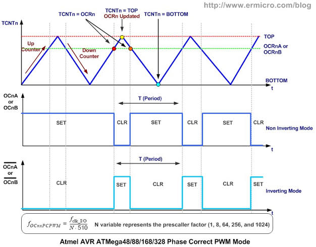
Ivan wrote:I expect the compare register is 8 bit wide.dare4444 wrote:The second PWM mode is called phase-correct PWM. In this mode, the timer counts from 0 to 255 and then back down to 0. The output turns off as the timer hits the output compare register value on the way up, and turns back on as the timer hits the output compare register value on the way down.
The PWM seems to be inverted in your description:
register D9 resp. D10
value
0xFF permanent L or needle pulses to H
0x7F or 0x80 rectangles 1:1
0x00 permanent H or needle pulses to L
The output belonging to the upper byte (say D9) sends narrow pulses from H to L only, the values being limited to 0x00, 0x01, 0x02 and 0x03. When D9 is H (most of the time), inverted pulses from D10 are present on the NAND output. When D9 is L, the NAND output is held in H. It is not a PWM representation of the AF input with 10 bit resolution, it is something strange...
VBR from Ivan
Oh. ADC is 10 bit. Each output starts with most significant bit and least significant bit and spits out the binary byte one after other, like 8 bit + 8 bit? In software there's a function called union. High and low byte are combined in a single integer. Is it gonna be of any use? I know that two 8 bit binary numbers can be subtracted for one 8 bit output. Could you explain more about this highbyte and lowbyte ?
dare4444- Posts : 427
Join date : 2013-03-19
Re: High Quality 16 bit AM PWM Arduino TX
![]() by Ivan Tue Feb 08, 2022 10:16 pm
by Ivan Tue Feb 08, 2022 10:16 pm
I expect the compare register is 8 bit wide.dare4444 wrote:The second PWM mode is called phase-correct PWM. In this mode, the timer counts from 0 to 255 and then back down to 0. The output turns off as the timer hits the output compare register value on the way up, and turns back on as the timer hits the output compare register value on the way down.
The PWM seems to be this way according to your description:
register D9 resp. D10
value
0x00 permanent L
0x01 needle pulses L to H (the output switches on and after two clocks off)
0x7F or 0x80 rectangles 1:1
0xFE needle pulses H to L (the output switches off and after two clocks on)
0xFF permanent H
The output belonging to the upper byte (say D9) sends narrow pulses from L to H only, the values being limited to 0x00, 0x01, 0x02 and 0x03. When D9 is H (short time only), inverted pulses from D10 are present on the NAND output. When D9 is L (most of the time), the NAND output is held in H. It is not a PWM representation of the AF input with 10 bit resolution, it is something strange...
VBR from Ivan
Last edited by Ivan on Tue Feb 08, 2022 10:42 pm; edited 3 times in total
Ivan- Posts : 793
Join date : 2012-11-25
Age : 64
Location : Praha, Czechia
Re: High Quality 16 bit AM PWM Arduino TX
![]() by dare4444 Tue Feb 08, 2022 9:28 pm
by dare4444 Tue Feb 08, 2022 9:28 pm
It starts logic 1 at the bottom of the first slope.
When it's matched on way up it switches to 0.
The other slope is also at zero.
00 = 1 (Nand)
On its way down on the second slope it's matched again and timer turns on or 1 and nand gate outputs goes zero.
Two slopes are effectively combined in the gate as there are two output pins D9 and D10 for each slope.
dare4444- Posts : 427
Join date : 2013-03-19
Re: High Quality 16 bit AM PWM Arduino TX
![]() by dare4444 Tue Feb 08, 2022 9:12 pm
by dare4444 Tue Feb 08, 2022 9:12 pm
Yes, it's a 10 bit ADC. I have hit a mental block.Ivan wrote:Are you sure? I expect a 16-bit ADC generates a two-byte (word) unsigned number, representing the input level this way:dare4444 wrote:D9 counts up from 0 to 255 and D10 counts low from 255 to 0. It's a dual slope PWM which is then converted into two separate pulses on D9 and D10.
0 V 0x0000
Vref/2 0x7FFF or 0x8000
Vref 0xFFFF
Does the Arduino have a 16-bit ADC, whose output is truncated to 10 bits, or the ADC is 10 bits only? Then it is this way:
0 V 0x0000
Vref/2 0x01FF or 0x0200
Vref 0x03FF
The two bytes are separately represented as pulses of different width:
0x00 permanent L or needle pulses to H
0x7F or 0x80 rectangles 1:1
0xFF permanent H or needle pulses to L
These pulses are output to D9 and D10 respectively.
Note that in the case of a 10-bit ADC the output belonging to the upper byte sends narrow pulses only, the values being limited to 0x00, 0x01, 0x02 and 0x03.
Am I right?
VBR Ivan
dare4444- Posts : 427
Join date : 2013-03-19
Re: High Quality 16 bit AM PWM Arduino TX
![]() by Ivan Tue Feb 08, 2022 7:52 pm
by Ivan Tue Feb 08, 2022 7:52 pm
Are you sure? I expect a 16-bit ADC generates a two-byte (word) unsigned number, representing the input level this way:dare4444 wrote:D9 counts up from 0 to 255 and D10 counts low from 255 to 0. It's a dual slope PWM which is then converted into two separate pulses on D9 and D10.
0 V 0x0000
Vref/2 0x7FFF or 0x8000
Vref 0xFFFF
Does the Arduino have a 16-bit ADC, whose output is truncated to 10 bits, or the ADC is 10 bits only? Then it is this way:
0 V 0x0000
Vref/2 0x01FF or 0x0200
Vref 0x03FF
The two bytes are separately represented as pulses of different width:
0x00 permanent L or needle pulses to H
0x7F or 0x80 rectangles 1:1
0xFF permanent H or needle pulses to L
These pulses are output to D9 and D10 respectively.
Note that in the case of a 10-bit ADC the output belonging to the upper byte sends narrow pulses only, the values being limited to 0x00, 0x01, 0x02 and 0x03.
Am I right?
VBR Ivan
Ivan- Posts : 793
Join date : 2012-11-25
Age : 64
Location : Praha, Czechia
Re: High Quality 16 bit AM PWM Arduino TX
![]() by Ivan Tue Feb 08, 2022 5:19 pm
by Ivan Tue Feb 08, 2022 5:19 pm
NO, NO, NO!!! ((((A+B)')'+C)')' = A+B+C The circuit is functionally the same as a three-input AND gate. Where is the 256:1 weighting?!dare4444 wrote:This is how I think both D9 and D10 would be combined correctly in four nand gates. I've posted two wave forms of the output.
VBR Ivan
Ivan- Posts : 793
Join date : 2012-11-25
Age : 64
Location : Praha, Czechia
Re: High Quality 16 bit AM PWM Arduino TX
![]() by Ivan Tue Feb 08, 2022 5:13 pm
by Ivan Tue Feb 08, 2022 5:13 pm
This will not help. The average counts with equal weight of both signals. You need a weighted "average" with 256:1 weight ratio!! And a NAND function of two synchronous PWM signals outputs inversion of those input pulses, which are narrower - not the average. A NAND function of two asynchronous PWM signals outputs random wide pulses depending on the phase shift of inputs.dare4444 wrote: Need a NAND gate to first combine the two pwm signals and therefore their average power by their on/off time. IThe new pwm output is the average on/off time of two.
VBR Ivan
Last edited by Ivan on Tue Feb 08, 2022 7:32 pm; edited 1 time in total
Ivan- Posts : 793
Join date : 2012-11-25
Age : 64
Location : Praha, Czechia
Re: High Quality 16 bit AM PWM Arduino TX
![]() by Ivan Tue Feb 08, 2022 5:08 pm
by Ivan Tue Feb 08, 2022 5:08 pm
Combining the two signals on RC network yields time integral of the weighted sum of both signals. The capacitor is also essential! The result would be an (analog) replica of the input signal with some quantization noise. It is unusable as an input of a gate, resp if you omited the MCU and fed the AF signal directly into the gate, you would obtain the same crap result.dare4444 wrote:We know it could generate a a linear voltage when combined in 256:1 resistors. Now we just need to do it digitally. I still don't understand the concept. Maybe my circuit needs a change.
You need to combine the two PWM signals keeping the 256:1 weighting. How? I do not know. Maybe sequentially: to output 256 times the pulse of MSB and then the LSB pulse once per sample. To process 32 Ksamples per second it would require repetition rate of width modulated pulses more than 8,2 MHz - too much for Arduino's 16 MHz clock.
VBR Ivan
Ivan- Posts : 793
Join date : 2012-11-25
Age : 64
Location : Praha, Czechia
Re: High Quality 16 bit AM PWM Arduino TX
![]() by dare4444 Tue Feb 08, 2022 5:06 pm
by dare4444 Tue Feb 08, 2022 5:06 pm
00 = 1
01 = 0
10 = 0
11= 0
Truth Table for 74HC00 Nand gates

dare4444- Posts : 427
Join date : 2013-03-19

dare4444- Posts : 427
Join date : 2013-03-19
Re: High Quality 16 bit AM PWM Arduino TX
![]() by dare4444 Tue Feb 08, 2022 11:35 am
by dare4444 Tue Feb 08, 2022 11:35 am
Last edited by dare4444 on Tue Feb 08, 2022 2:05 pm; edited 3 times in total
dare4444- Posts : 427
Join date : 2013-03-19
dare4444- Posts : 427
Join date : 2013-03-19
Re: High Quality 16 bit AM PWM Arduino TX
![]() by dare4444 Tue Feb 08, 2022 11:03 am
by dare4444 Tue Feb 08, 2022 11:03 am
We know it could generate a a linear voltage when combined in 256:1 resistors. Now we just need to do it digitally. I still don't understand the concept. Maybe my circuit needs a change.
dare4444- Posts : 427
Join date : 2013-03-19
Re: High Quality 16 bit AM PWM Arduino TX
![]() by Ivan Tue Feb 08, 2022 7:47 am
by Ivan Tue Feb 08, 2022 7:47 am
VBR from Ivan
Ivan- Posts : 793
Join date : 2012-11-25
Age : 64
Location : Praha, Czechia
Re: High Quality 16 bit AM PWM Arduino TX
![]() by dare4444 Tue Feb 08, 2022 12:38 am
by dare4444 Tue Feb 08, 2022 12:38 am
dare4444- Posts : 427
Join date : 2013-03-19
Re: High Quality 16 bit AM PWM Arduino TX
![]() by dare4444 Sun Feb 06, 2022 10:48 pm
by dare4444 Sun Feb 06, 2022 10:48 pm
dare4444- Posts : 427
Join date : 2013-03-19
Re: High Quality 16 bit AM PWM Arduino TX
![]() by dare4444 Sun Feb 06, 2022 8:50 pm
by dare4444 Sun Feb 06, 2022 8:50 pm
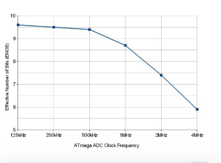
Speed: PreScaler: Time: Freq: ActFrq: BitsRes:
120KHz 128 116us 9.6ksps 9.6ksps 10b
240KHz 64 60us 19ksps 19ksps 10b
500KHz 32 36us 38ksps 38ksps 10b
1MHz 16 20us 77ksps 50ksps 9b
2MHz 8 13us 154ksps 77ksps 8b
4MHz 4 9us 308ksps 111ksps 6b
8MHz 2 7us 615ksps ? ?
ARDUINO ADC Speeds (with 20MHz Clock) :
Speed: PreScaler: Time: Freq: ActFrq: BitsRes:
1MHz 16 90ksps 9b
2MHz 8 170ksps 8b
4MHz 4 350ksps 6b
8MHz 2 615ksps ?
ARDUINO ADC Speeds (with 32MHz Clock) :
Speed: PreScaler: Time: Freq: ActFrq: BitsRes:
1MHz 16 150ksps 9b
2MHz 8 300ksps 8b
4MHz 4 600ksps 6b
8MHz 2 1.2Msps ?
dare4444- Posts : 427
Join date : 2013-03-19
Re: High Quality 16 bit AM PWM Arduino TX
![]() by dare4444 Sun Feb 06, 2022 1:28 pm
by dare4444 Sun Feb 06, 2022 1:28 pm
http://adc_to_pwm.pde
// ADC to PWM AM TX
// takes in audio data from ADC pin A0 and generates PWM at D9 and D10
// Timer1 PWM 16 bit, Phase Correct mode, frequency at each pin 31.25kHz - output D9 & D10 are added together for 8 bit + 8 bit = 16 bit audio resolution. Sampling frequency is 64KHz (adc clk/ 14 cycles) which gives an audio bandwidth of 20Hz to 20KHz
#define PWM_FREQ 0x00FF // pwm frequency count - 255 or 11111111 // sets resolution for each 8 bit data
#define PWM_MODE 0 // Fast (1) or Phase Correct (0)
#define PWM_QTY 2 // number of pwms are 2
void setup() {
//Set up pin 6 for 1600KHz carrier out with 50% duty cycle
pinMode(5, OUTPUT);
pinMode(6,OUTPUT);
TCCR0A=0;//reset the A register for timer0
TCCR0B=0;//reset the B register for timer0
TCCR0A=0b01010011;// fast pwm mode on pin 5 & 6
TCCR0B=0b00001001;// no prescaler and WGM02 is 1
OCR0A=9;//control value, sets frequency to 1600KHz or 16MHz / (OCR0A+1)
//Carrier has been set
// setup ADC Analog Input Pin A0
ADMUX = 0x60; // left adjust, selects A0 as adc input pin, internal vcc
ADCSRA = 0xe4; // turn on adc, sets prescaler to 16MHz clock / 16 = 1MHz ADC speed in free running mode, auto trigger
ADCSRB =0x07; // t1 capture for trigger
DIDR0 = 0x01; // turn off digital inputs for adc0 or pin A0
// setup PWM
TCCR1A = (((PWM_QTY - 1) << 5) | 0x80 | (PWM_MODE << 1)); //
TCCR1B = ((PWM_MODE << 3) | 0x11); // ck/1
TIMSK1 = 0x20; // interrupt on capture interrupt
ICR1H = (PWM_FREQ >>
ICR1L = (PWM_FREQ & 0xff); // Total 8+8 = 16 bit
DDRB |= ((PWM_QTY << 1) | 0x02); // turn on outputs
sei(); // turn on interrupts - not really necessary with arduino
}
void loop() {
while(1); // gets rid of jitter for smooth pwm
ISR(TIMER1_CAPT_vect) {
// get ADC data
unsigned int temp1 = ADCL; // fetch low byte first
unsigned int temp2 = ADCH; // fetch high byte
// ADCH and ADCL 8 bits each are represented
// output high byte on OC1A
OCR1AH = temp2 >> 8; // takes top 8 bits
OCR1AL = temp2; // takes bottom 8 bits
// output low byte on OC1B
OCR1BH = temp1 >> 8;
OCR1BL = temp1;
//top 8 and bottom 8 audio bits as 31.25KHz PWM square waves are combined together in four input nand gate CD4012 along with the 1600KHz carrier frequency from D6. The sampling frequency is 64KHz which is good great for this AM transmitter. The second nand gate inverts the output signal to positive or logic 1 and drives a totem pole output stage for low impedance output. Add a 5 pole low pass filter to remove the harmonics before transmitting. Arduino is a $4 Nano version.
}
}
Last edited by dare4444 on Tue Feb 08, 2022 12:31 am; edited 5 times in total
dare4444- Posts : 427
Join date : 2013-03-19
Re: High Quality 16 bit AM PWM Arduino TX
![]() by dare4444 Sat Feb 05, 2022 12:19 pm
by dare4444 Sat Feb 05, 2022 12:19 pm
Maximum Arduino PWM of 62.5KHz with a 16MHz system clock when resolution is 8 bit or 256.
"The maximum frequency that can be input to the timers are the Arduino clock frequency, that means 16MHz on most Arduino processors, with a 216 step PWM it implies the PWM frequency will be 16000000/216 i.e. 244.14Hz, that is fast enough for brightness regulation"
dare4444- Posts : 427
Join date : 2013-03-19
Re: High Quality 16 bit AM PWM Arduino TX
![]() by Ivan Sat Feb 05, 2022 8:28 am
by Ivan Sat Feb 05, 2022 8:28 am
I see you already have found the answer by yourself. You must combine the two PWMs digitally, in a gate! You omit the capacitor and both resistors as well.dare4444 wrote:Harry, Ivan please check my question
I am not sure whether the 4013 must be used. The two PWMs are kept in sync by the internal clock of the Arduino. In that case a half of 4012 would do all the job:
PWM1 to input 1
PWM2 to input 2
carrier to input 3
Vcc to input 4
VBR from Ivan
Ivan- Posts : 793
Join date : 2012-11-25
Age : 64
Location : Praha, Czechia
Re: High Quality 16 bit AM PWM Arduino TX
![]() by Ivan Sat Feb 05, 2022 8:14 am
by Ivan Sat Feb 05, 2022 8:14 am
Hi, I am not experienced much in the assembler level of Arduino programming. I may be wrong, but I have some doubts about the PWM generator - see the source listing.dare4444 wrote: // get ADC data
unsigned int temp1 = ADCL; // fetch low byte first
unsigned int temp2 = ADCH; // fetch high byte
?? UNSIGNED INT holds two bytes, I expect the upper byte of both temp1 and temp2 is 0x00 if they are loaded with one byte
// output high byte on OC1A
OCR1AH = temp2 >> 8; // takes top 8 bits ?? always 0x00 ?
OCR1AL = temp2; // takes bottom 8 bits
// output low byte on OC1B
OCR1BH = temp1 >> 8; ?? always 0x00 ?
OCR1BL = temp1;
?? why not simply OCR1BH:OCR1BL = temp1 as a 16 bit value?
VBR Ivan
Ivan- Posts : 793
Join date : 2012-11-25
Age : 64
Location : Praha, Czechia
dare4444- Posts : 427
Join date : 2013-03-19
Re: High Quality 16 bit AM PWM Arduino TX
![]() by dare4444 Sat Feb 05, 2022 7:52 am
by dare4444 Sat Feb 05, 2022 7:52 am
These are characteristics of FM
FM has a signal to noise ratio of about 60dB. That can be managed by a bit depth of 10 bits.
FM has an audio bandwidth up to 15 kHz, so a sample rate of over 30 kHz is required - 32,768 Hz is a nice power of 2 that fits the bill.
So 10 bits per sample, 32,768 samples per second, 2 stereo channels - that’s a total bit rate of 655,360 bits per second (655 kbps).
Human ear dynamic range = 90dB when apartment has other noises like traffic, AC, etc.
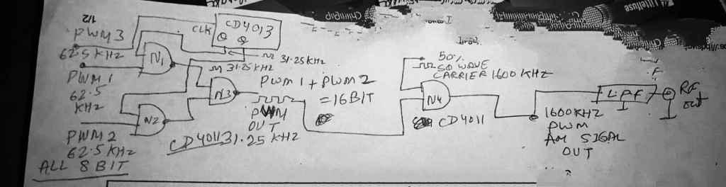
Solution might be to take 2 digital pwm pulses and merge in xor gate using nand gates.
8 bit each. Arduino has 3 timers. 16 mhz /256 = 62.5 khz pwm from each timer. The timers are fed from a single audio source. We need 16 bit. So we combine the two pwm signal in two nand gates. The other pins of the nand gates are fed from a flip flop or divide by 2 . The third pwm signal is driving the flip flop so that the clock pulses remain synchronized. The output of two nand gates now merge into one nand gate. Its output is 62.5/2 = 31.25KHz 16 bit PWM audio signal. Even if 2 bits are lost to error it doesn't matter as 12-14 bit resolution is all we can hear (99%).
dare4444- Posts : 427
Join date : 2013-03-19
Re: High Quality 16 bit AM PWM Arduino TX
![]() by dare4444 Sat Feb 05, 2022 1:04 am
by dare4444 Sat Feb 05, 2022 1:04 am
dare4444- Posts : 427
Join date : 2013-03-19
Re: High Quality 16 bit AM PWM Arduino TX
![]() by dare4444 Fri Feb 04, 2022 8:40 pm
by dare4444 Fri Feb 04, 2022 8:40 pm
Ivan,
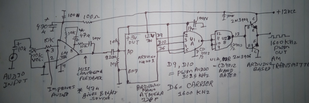
Question is, if we don't want an analogue output then removing the capacitor would give me digital 16 bit resolution PWM, am I right? I am trying to build an AM where the 16 bit digital signal is going to a 74hc00 on one input pin and other input pin is fed with 1600KHz carrier wave to generate 1600KHz PWM at 74HC00 output to drive a MOSFET in class D or a low pass filter feeding an antenna. I can remove the capacitor right for 16 bit digital pwm signal? Analogue has no use here.
My only doubt.
dare4444- Posts : 427
Join date : 2013-03-19
Re: High Quality 16 bit AM PWM Arduino TX
![]() by dare4444 Fri Feb 04, 2022 2:44 pm
by dare4444 Fri Feb 04, 2022 2:44 pm
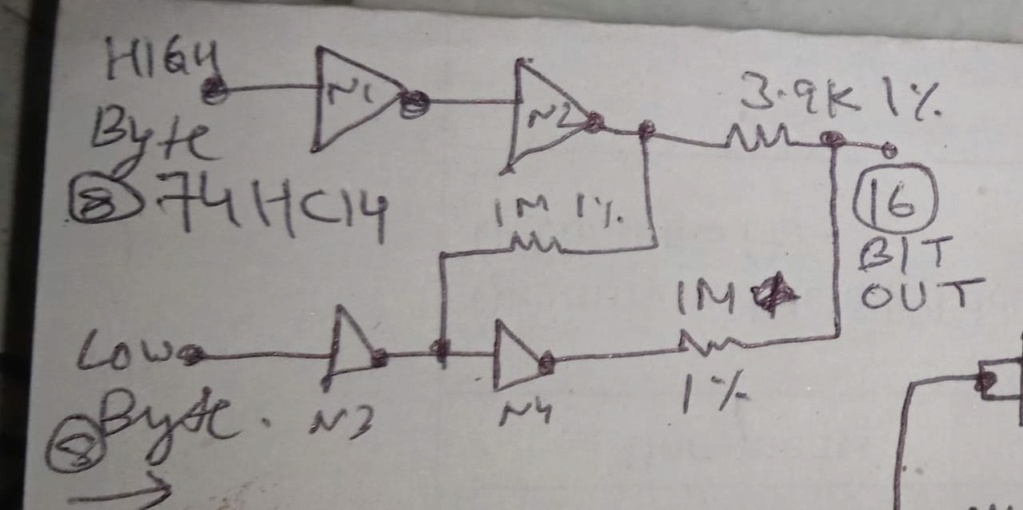
The inverters are needed to give some current
boost and also cancel out some errors which may be there.
The 1M between the top and below inverters is there to cancel some of them out.
dare4444- Posts : 427
Join date : 2013-03-19
Re: High Quality 16 bit AM PWM Arduino TX
![]() by dare4444 Fri Feb 04, 2022 12:37 pm
by dare4444 Fri Feb 04, 2022 12:37 pm
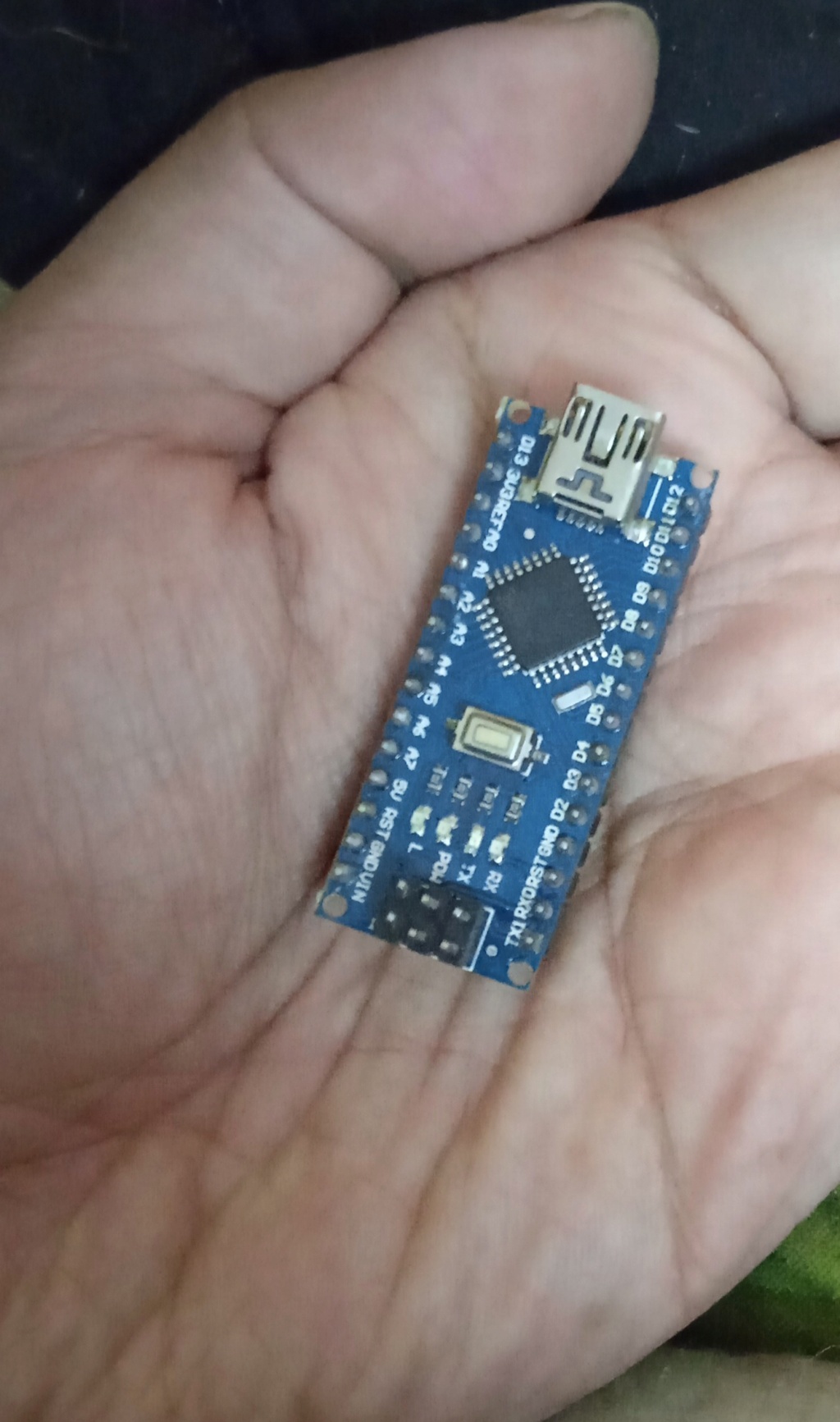
Arduino Nano. Other one eliminated. Two separate codes have been merged now on a single Nano. Touching D6 for carrier giving a light hiss on radio. Obviously the signal is very very weak and not travelling even a foot when I touch D6 with my multimeter probe. D9 and D10 are the 31.25KHz PWM pins.
Testing results will be posted soon.
dare4444- Posts : 427
Join date : 2013-03-19
Re: High Quality 16 bit AM PWM Arduino TX
![]() by dare4444 Thu Feb 03, 2022 10:23 pm
by dare4444 Thu Feb 03, 2022 10:23 pm
pinMode(5, OUTPUT);
pinMode(6,OUTPUT);
TCCR0A=0;//reset the register
TCCR0B=0;//reset tthe register
TCCR0A=0b01010011;// fast pwm mode
TCCR0B=0b00001001;// no prescaler and WGM02 is 1
OCR0A=0;//control value
}
When OCR0A=9 then output frequency would be 1600KHz at 50% square wave.
The code above has to be there after void setup.
It uses timer0 or pins 5 & 6. Timer1 is being used by the pwm modulator.
Putting it on Arduino 1 and taking carrier signal from D6, the other Arduino 2 could be eliminated. This code is outside the loop so it won't interfere with interrupts or other stuff
dare4444- Posts : 427
Join date : 2013-03-19
Re: High Quality 16 bit AM PWM Arduino TX
![]() by dare4444 Thu Feb 03, 2022 8:26 pm
by dare4444 Thu Feb 03, 2022 8:26 pm
ICR1H = (PWM_FREQ >>
Where the smiley face is, the number '8' should be there followed by a ')' with no space between the two.
This completes the project. Have fun building it.
dare4444- Posts : 427
Join date : 2013-03-19
Re: High Quality 16 bit AM PWM Arduino TX
![]() by dare4444 Thu Feb 03, 2022 8:25 pm
by dare4444 Thu Feb 03, 2022 8:25 pm
Arduino 1
// adc_to_pwm.pde
// ADC to PWM converter
// takes in audio data from the ADC and generates PWM at D9 and D10
// Timer1 PWM. 16 bit, Phase Correct, 31.25kHz - although ADC is 10 bit, in real time use & high sampling freq we get 8 bit only, output D9 & D10 are added together for 8 + 8 = 16 bit resolution. Sampling frequency is 38KHz (adc clk/ 13 cycles)
It would be hard to differentiate between CD player sound and this transmitter
#define PWM_FREQ 0x00FF // pwm frequency count - 255 or 11111111
#define PWM_MODE 0 // Fast (1) or Phase Correct (0)
#define PWM_QTY 2 // number of pwms are 2, each timer has 2 counters
void setup() {
// setup ADC Analog Input Pin A0
ADMUX = 0x60; // left adjust, selects A0 as adc input pin, internal vcc
ADCSRA = 0xe5; // turn on adc, sets prescaler to 16MHz clock / 32 = 500KHz ADC speed also known as free running mode, auto trigger
ADCSRB =0x07; // t1 capture for trigger
DIDR0 = 0x01; // turn off digital inputs for adc0 or pin A0
// setup PWM
TCCR1A = (((PWM_QTY - 1) << 5) | 0x80 | (PWM_MODE << 1)); //
TCCR1B = ((PWM_MODE << 3) | 0x11); // ck/1
TIMSK1 = 0x20; // interrupt on capture interrupt
ICR1H = (PWM_FREQ >>
ICR1L = (PWM_FREQ & 0xff); // & 0xff is hexadecimal numeric 16, adc clock freq is 500KHz, pwm frequency 500/16 - 31.25KHz
DDRB |= ((PWM_QTY << 1) | 0x02); // turn on outputs
sei(); // turn on interrupts - not really necessary with arduino
}
void loop() {
while(1); // gets rid of jitter for smooth pwm
}
ISR(TIMER1_CAPT_vect) {
// get ADC data
unsigned int temp1 = ADCL; // fetch low byte first
unsigned int temp2 = ADCH; // fetch high byte
// ADCH and ADCL 8 bits each are represented
// output high byte on OC1A
OCR1AH = temp2 >> 8; // takes top 8 bits
OCR1AL = temp2; // takes bottom 8 bits
// output low byte on OC1B
OCR1BH = temp1 >> 8;
OCR1BL = temp1;
// top 8 and bottom 8 bits are combined together in two precision resistors at pin D9 and D10 for 16 bit of audio resolution riding on a 31.25KHz PWM modulated square wave, sampling frequency is 38KHz, good enough for an AM transmitter!
}
dare4444- Posts : 427
Join date : 2013-03-19
Page 1 of 2 • 1, 2 ![]()
» Arduino etc. (was: GRID DIP OSCILLATOR)
» Two Arduino Nano Based AM PWM TX
» Fm tx audio quality
» New project on sm0vpo.com - Arduino based Radio Control Transmitter Coder
|
|
|