2n7000 102MHz amp


Re: 2n7000 102MHz amp
![]() by dare4444 Wed Aug 26, 2020 9:09 am
by dare4444 Wed Aug 26, 2020 9:09 am
dare4444- Posts : 427
Join date : 2013-03-19
Re: 2n7000 102MHz amp
![]() by dare4444 Tue Aug 25, 2020 9:35 pm
by dare4444 Tue Aug 25, 2020 9:35 pm
dare4444- Posts : 427
Join date : 2013-03-19
Re: 2n7000 102MHz amp
![]() by Ivan Tue Aug 25, 2020 2:52 pm
by Ivan Tue Aug 25, 2020 2:52 pm
schematics for two last posts do not display to me. Maybe there are too many pics in this thread?
BR Ivan
Ivan- Posts : 796
Join date : 2012-11-25
Age : 64
Location : Praha, Czechia
Re: 2n7000 102MHz amp
![]() by dare4444 Mon Aug 24, 2020 10:13 pm
by dare4444 Mon Aug 24, 2020 10:13 pm
Last edited by dare4444 on Mon Feb 21, 2022 6:36 pm; edited 1 time in total
dare4444- Posts : 427
Join date : 2013-03-19
Re: 2n7000 102MHz amp
![]() by dare4444 Sun Aug 23, 2020 9:15 pm
by dare4444 Sun Aug 23, 2020 9:15 pm
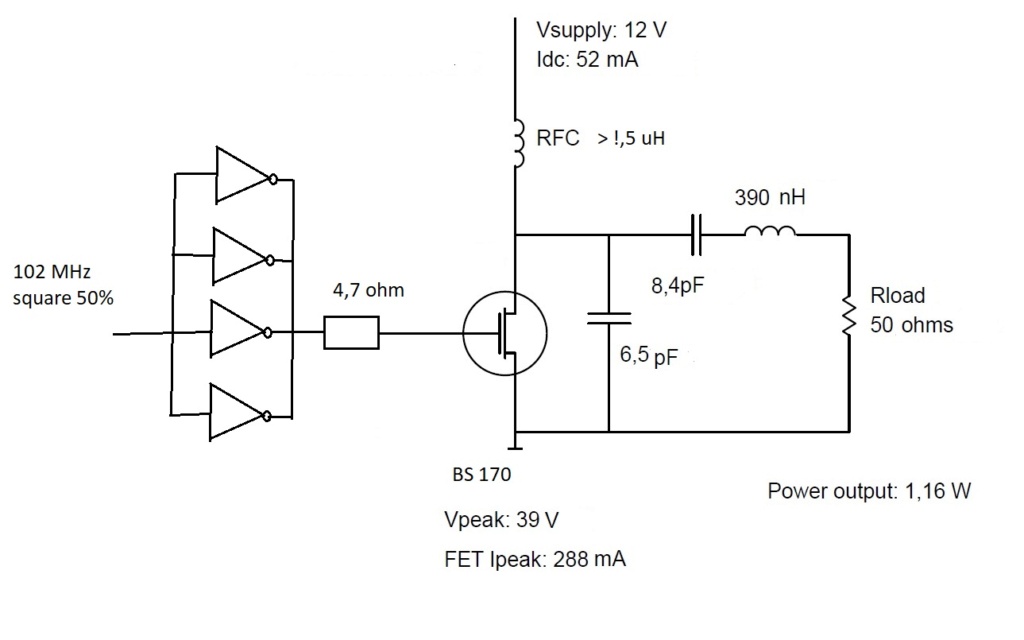
2sc1971 FM power transistor is now obsolete. This amplifier uses one 2n3904 preamp, two mosfet driver stage, to drive 5ohm input impedance of four mosfet PA stage, for 4.8W output with 856ma of final stage current. 15mW in gave 4.8W out at 100MHz. In real life I would use BS170 instead of 2n7000.
dare4444- Posts : 427
Join date : 2013-03-19
Re: 2n7000 102MHz amp
![]() by dare4444 Sun Aug 23, 2020 9:13 pm
by dare4444 Sun Aug 23, 2020 9:13 pm
Last edited by dare4444 on Thu Mar 03, 2022 6:32 pm; edited 1 time in total
dare4444- Posts : 427
Join date : 2013-03-19
Re: 2n7000 102MHz amp
![]() by dare4444 Sun Aug 23, 2020 9:11 pm
by dare4444 Sun Aug 23, 2020 9:11 pm
Last edited by dare4444 on Tue May 10, 2022 12:22 am; edited 1 time in total
dare4444- Posts : 427
Join date : 2013-03-19
Re: 2n7000 102MHz amp
![]() by dare4444 Sun Aug 23, 2020 8:18 am
by dare4444 Sun Aug 23, 2020 8:18 am
Last edited by dare4444 on Thu Mar 03, 2022 6:41 pm; edited 1 time in total
dare4444- Posts : 427
Join date : 2013-03-19
Re: 2n7000 102MHz amp
![]() by dare4444 Sat Aug 22, 2020 8:22 pm
by dare4444 Sat Aug 22, 2020 8:22 pm
Last edited by dare4444 on Thu Mar 03, 2022 6:39 pm; edited 1 time in total
dare4444- Posts : 427
Join date : 2013-03-19
Re: 2n7000 102MHz amp
![]() by Ivan Sat Aug 22, 2020 7:35 am
by Ivan Sat Aug 22, 2020 7:35 am
we generally do not want resistors in RF PAs, as they represent wasted power (converted to heat). On the other hand, a strategically placed resistor may help us to trade some gain for stability, so it may be used where necessary.
Conjugate match should be used to achieve maximum transfer of RF power.
2N7000 and BS170 seem to be much similar, but BS170 are a bit faster. Both types are IMHO designed primarily as switches of low-power peripherals of logic circuits, interfacing 3.3V and 5V logic outputs to relays, lights, buzzers etc.
BR from Ivan
Ivan- Posts : 796
Join date : 2012-11-25
Age : 64
Location : Praha, Czechia
Re: 2n7000 102MHz amp
![]() by dare4444 Fri Aug 21, 2020 9:15 pm
by dare4444 Fri Aug 21, 2020 9:15 pm
When I build it I'll use BS170. There shouldn't be any major differences with simulation with 2n7000 and real life use with BS170 right? Both are similar except that BS170 works way better.
The lower the driver impedance the better?
dare4444- Posts : 427
Join date : 2013-03-19
Re: 2n7000 102MHz amp
![]() by dare4444 Fri Aug 21, 2020 4:05 pm
by dare4444 Fri Aug 21, 2020 4:05 pm
Last edited by dare4444 on Thu Mar 03, 2022 6:45 pm; edited 1 time in total
dare4444- Posts : 427
Join date : 2013-03-19
dare4444- Posts : 427
Join date : 2013-03-19
Re: 2n7000 102MHz amp
![]() by dare4444 Fri Aug 21, 2020 1:07 pm
by dare4444 Fri Aug 21, 2020 1:07 pm
Last edited by dare4444 on Thu Mar 03, 2022 6:47 pm; edited 4 times in total
dare4444- Posts : 427
Join date : 2013-03-19
Re: 2n7000 102MHz amp
![]() by Ivan Fri Aug 21, 2020 8:09 am
by Ivan Fri Aug 21, 2020 8:09 am
the FETs in this schematics IMHO do not run in switching mode (they are biased to the threshold of opening), so it is a very different case from an E class amplifier. The efficiency is somewhat worse, but the amplifier works.
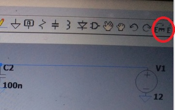
About the flip and rotate icons in LTspice editor: they are grayed and off normally. They become activated when you have a "sprited" symbol only, i.e. one selected for moving or dragging. Try it!
BR from Ivan
P.S: The paragraph I reacted to now disappeared. How strange... Maybe Dare is just editing it.
Ivan- Posts : 796
Join date : 2012-11-25
Age : 64
Location : Praha, Czechia
Re: 2n7000 102MHz amp
![]() by Ivan Thu Aug 20, 2020 7:32 pm
by Ivan Thu Aug 20, 2020 7:32 pm
Here are the icons to rotate and flip components, if you prefer icons to hotkeys.dare4444 wrote:Yes, I couldn't understand how to rotate the components.
BR from Ivan
Ivan- Posts : 796
Join date : 2012-11-25
Age : 64
Location : Praha, Czechia
Re: 2n7000 102MHz amp
![]() by dare4444 Thu Aug 20, 2020 4:30 pm
by dare4444 Thu Aug 20, 2020 4:30 pm
Last edited by dare4444 on Tue May 10, 2022 12:22 am; edited 1 time in total
dare4444- Posts : 427
Join date : 2013-03-19
Re: 2n7000 102MHz amp
![]() by dare4444 Thu Aug 20, 2020 8:53 am
by dare4444 Thu Aug 20, 2020 8:53 am
Last edited by dare4444 on Tue May 10, 2022 12:26 am; edited 1 time in total
dare4444- Posts : 427
Join date : 2013-03-19
Re: 2n7000 102MHz amp
![]() by admin Wed Aug 19, 2020 7:25 pm
by admin Wed Aug 19, 2020 7:25 pm
It is looking really good. Also good that you are using LTspice to simulate. I found that I can draw circuits for the homepages really quickly, then do a screen dump.
One small point, I notice that all your components are vertical. Are you aware that if you select a component, before you "plant it" you can mirror and rotate with Ctrl+E and Ctrl+R ?
Good project :-)
BR Harry
_________________
Everything in this world is either bacon, or it isn't bacon
They say that money cannot bring you happiness, but if you have it then you can always buy more bacon

admin- Admin
- Posts : 1144
Join date : 2012-11-24
Age : 72
Location : Märsta, Sweden -

Re: 2n7000 102MHz amp
![]() by dare4444 Wed Aug 19, 2020 11:34 am
by dare4444 Wed Aug 19, 2020 11:34 am
Last edited by dare4444 on Tue May 10, 2022 12:25 am; edited 1 time in total
dare4444- Posts : 427
Join date : 2013-03-19
Re: 2n7000 102MHz amp
![]() by dare4444 Wed Aug 19, 2020 7:43 am
by dare4444 Wed Aug 19, 2020 7:43 am
Last edited by dare4444 on Tue May 10, 2022 12:25 am; edited 1 time in total
dare4444- Posts : 427
Join date : 2013-03-19
Re: 2n7000 102MHz amp
![]() by dare4444 Sun Aug 16, 2020 7:02 am
by dare4444 Sun Aug 16, 2020 7:02 am
dare4444- Posts : 427
Join date : 2013-03-19
Ivan- Posts : 796
Join date : 2012-11-25
Age : 64
Location : Praha, Czechia
Re: 2n7000 102MHz amp
![]() by dare4444 Sat Aug 15, 2020 3:56 pm
by dare4444 Sat Aug 15, 2020 3:56 pm
Last edited by dare4444 on Tue May 10, 2022 12:24 am; edited 1 time in total
dare4444- Posts : 427
Join date : 2013-03-19
Re: 2n7000 102MHz amp
![]() by dare4444 Sat Aug 15, 2020 3:51 pm
by dare4444 Sat Aug 15, 2020 3:51 pm
Last edited by dare4444 on Tue May 10, 2022 12:24 am; edited 1 time in total
dare4444- Posts : 427
Join date : 2013-03-19
Re: 2n7000 102MHz amp
![]() by dare4444 Sat Aug 15, 2020 3:48 pm
by dare4444 Sat Aug 15, 2020 3:48 pm
I've just tested a single BS170 driven by my IC exciter. Class AB mode helps. I tried driving it directly with square waves but input current almost cooked the mosfet. Two PN2222As in parallel also gave me a watt of output.
dare4444- Posts : 427
Join date : 2013-03-19
Re: 2n7000 102MHz amp
![]() by Ivan Fri Aug 14, 2020 6:51 pm
by Ivan Fri Aug 14, 2020 6:51 pm
https://www.google.com/url?sa=t&rct=j&q=&esrc=s&source=web&cd=&cad=rja&uact=8&ved=2ahUKEwiy-dfHkJvrAhVQKuwKHeonAgEQFjALegQIARAB&url=https%3A%2F%2Fwww.wolfspeed.com%2Fdownloads%2Fdl%2Ffile%2Fid%2F536%2Fproduct%2F0%2Fclass_e_silicon_carbide_vhf_power_amplifier.pdf&usg=AOvVaw3hcxRENwK29xJ9I3USGpzC
https://www.semanticscholar.org/paper/An-LDMOS-VHF-class-E-power-amplifier-using-a-high-Q-Zirath-Rutledge/06c1d3187e9c0f4ee2a915e54ce5495d15ef7e21
and others. Miracles with cheap low-power devices happen rarely.
BR from Ivan
Ivan- Posts : 796
Join date : 2012-11-25
Age : 64
Location : Praha, Czechia
Re: 2n7000 102MHz amp
![]() by dare4444 Fri Aug 14, 2020 6:26 pm
by dare4444 Fri Aug 14, 2020 6:26 pm
dare4444- Posts : 427
Join date : 2013-03-19
Re: 2n7000 102MHz amp
![]() by Ivan Fri Aug 14, 2020 9:56 am
by Ivan Fri Aug 14, 2020 9:56 am
Assumingdare4444 wrote:How about this calculator? When I increase Po to 4W then C is 19p
https://people.physics.anu.edu.au/~dxt103/calculators/class-e.php
Q = 5
Vcc = 12 V
Vo = 1.4 V
f = 102 000 kHz
RFC = 0.0015 mH
like in my pravious calculation and
Po = 4 W,
the results are:
C1 = 23.5 pF (typ. Cds = 15 pF and 8.5 pF external capacitor)
C2 = 28.6 pF
L2 = 113 nH
Icc >= 380 mA
Ids = 3 Icc = 1.14 A (!!!)
Uds = 54 V
matching the output from 14.5 ohm to 50 ohm is required
The maximum Ids of BS170 will be exceeded.
The maximum Uds of BS170 will be approached.
The maximum efficiency of a E class PA is about 80%, so the power dissipation will be 1 W or more. This power will be converted to heat in the FET and partly in the coil. The power rating of BS170 will be exceeded.
Using two BS170 in parralel wil increase Cds to cca 30 pF, which is too much...
BR from Ivan
Last edited by Ivan on Fri Aug 14, 2020 6:36 pm; edited 1 time in total
Ivan- Posts : 796
Join date : 2012-11-25
Age : 64
Location : Praha, Czechia
Re: 2n7000 102MHz amp
![]() by dare4444 Fri Aug 14, 2020 1:07 am
by dare4444 Fri Aug 14, 2020 1:07 am
https://people.physics.anu.edu.au/~dxt103/calculators/class-e.php
dare4444- Posts : 427
Join date : 2013-03-19
Re: 2n7000 102MHz amp
![]() by Ivan Thu Aug 13, 2020 11:47 am
by Ivan Thu Aug 13, 2020 11:47 am
There is one problem, which may cause the amplifier not to work: the 6.5 pF capacitor includes the internal capacity between drain and source. That capacity is typically 15 pF. Even if you do not use any external capacitor in parralel, it is more than twice the value calculated.
The SW is not correct and reliable in any case. It calculated the DC input from the power source 0,6 W, while the RF output is almost two times bigger. I expect the DC current would be about 120 mA. Or did we invent a perpetuum mobile??
BR from Ivan
P.S. The exciter must be fully driven logic, not an open collector one.
Last edited by Ivan on Sat Aug 15, 2020 9:54 am; edited 1 time in total
Ivan- Posts : 796
Join date : 2012-11-25
Age : 64
Location : Praha, Czechia
Re: 2n7000 102MHz amp
![]() by Ivan Thu Aug 13, 2020 4:19 am
by Ivan Thu Aug 13, 2020 4:19 am
I am still browsing in the field of theory, which does not take all facts as a whole. It e.g. counts with zero rise and fall time of the FET resistance, which is far from reality. I do not feel to be ready to do the design - sorry.
It seems that square waveform with load factor 50% on the gate gives better efficiency of class E stages than the sinewave. Transitions between ON and OFF should be as fast as possible. I would try to connect the paralelled IC outputs to the FET gate via a small protective low inductance resistor (several ohms) only. Do not bother about harmonics, they are inherent to class E (and class C as well) and they are filtered at its output.
BR from Ivan
Ivan- Posts : 796
Join date : 2012-11-25
Age : 64
Location : Praha, Czechia
Re: 2n7000 102MHz amp
![]() by dare4444 Wed Aug 12, 2020 9:27 pm
by dare4444 Wed Aug 12, 2020 9:27 pm
Last edited by dare4444 on Thu Mar 03, 2022 6:43 pm; edited 1 time in total
dare4444- Posts : 427
Join date : 2013-03-19
Re: 2n7000 102MHz amp
![]() by Ivan Wed Aug 12, 2020 7:26 pm
by Ivan Wed Aug 12, 2020 7:26 pm
TNX for the link. The SW has two drawbacks:dare4444 wrote:Ivan,
I haven't used the software but here's the link
- it does not deal with the input circuitry (the gate driver) and
- it does not deal with output matching L network. Its coil may be combined with the resonant coil, reducing the number of parts. The PA can be designed to end with a given resistance, not an arbitrary one.
BR from Ivan
Ivan- Posts : 796
Join date : 2012-11-25
Age : 64
Location : Praha, Czechia
Re: 2n7000 102MHz amp
![]() by Ivan Wed Aug 12, 2020 7:08 pm
by Ivan Wed Aug 12, 2020 7:08 pm
Hi,dare4444 wrote:The low value coil in drain gives the highest output as it resonates with the output capacitance of BS170.
according to the models I have found the coil between the drain and the ouput should resonate with the output FET capacity plus it ensures the phase shift needed to minimize the losses plus it may be a part of the matching L network. It is calculated as a sum of three coils with different functions. The coil between the drain and Vcc acts as a choke, should be non-resonant on the 1st, 2nd, 3rd and 4th harmonics of the working frequency and should be much (at least 10x) bigger than the previous one.
Maybe you use another type of E class amplifier.
BTW what is the purpose of the (relatively big) resistors in the gate? Are they bound with the type of FET you use? They are omitted in schematics I have found.
BR from Ivan
Ivan- Posts : 796
Join date : 2012-11-25
Age : 64
Location : Praha, Czechia
Re: 2n7000 102MHz amp
![]() by dare4444 Wed Aug 12, 2020 4:39 pm
by dare4444 Wed Aug 12, 2020 4:39 pm
I was playing around with 2n7000 and the device is somewhat unstable at VHF. BS170 is better.
dare4444- Posts : 427
Join date : 2013-03-19
Re: 2n7000 102MHz amp
![]() by dare4444 Wed Aug 12, 2020 4:36 pm
by dare4444 Wed Aug 12, 2020 4:36 pm
I haven't used the software but here's the link
http://tonnesoftware.com/classe.html
For reference >> software and real life results https://ceworkbench.wordpress.com/2014/11/03/analyzing-a-failed-class-e-amplifier/amp/
dare4444- Posts : 427
Join date : 2013-03-19
Re: 2n7000 102MHz amp
![]() by Ivan Wed Aug 12, 2020 10:21 am
by Ivan Wed Aug 12, 2020 10:21 am
can you post a link to the SW you use? I am thinking of writing one, but it would be wasting time if it has been done already.
I expect a class E PA can be built for 100 MHz provided that the switching device is fast enough and the necessary inductors and capacitors are within the limits of realization (maybe as coax or stripline stubs).
Looking into the 2N7000 datasheet, I see rise time is 15 ns and fall time 8 ns. Considering the on time and off time being both cca 20ns, the limit frequency is about 16 MHz. This device is rather slow.
The input circuit may be critical. It must deliver enough current to charge/discharge the gate capacity very fast, so low impedance must be used or the gate-source capacity must be included into the matching circuit. The transistor should work in switching mode with fast transitions between ON and OFF state. I am still searching an optimum solution.
The choke between drain and Vcc must behave like an open circuit on the working frequency and its harmonics. Your coil has 53 ohms only, which is quite little.
You have no external capacitor between the drain and source. You thus rely on the internal capacity only. Is it OK?
BR from Ivan
Ivan- Posts : 796
Join date : 2012-11-25
Age : 64
Location : Praha, Czechia
Re: 2n7000 102MHz amp
![]() by dare4444 Wed Aug 12, 2020 9:23 am
by dare4444 Wed Aug 12, 2020 9:23 am
There's a free software for class E design. I ain't sure if class E is gonna work at 100MHz. What do you think?
Yesterday I received a bunch of mosfets from an indian components site. The newer 2n7000 fail to generate RF and are unstable. The BS170 solved the problem. It has a higher output current capacity (0.3A). It's much more stable than a 2n7000 and less problematic. They both have same input and output capacitance. I got half a watt of output with 26mW of drive. BS170 is the way to go. I think BS170 could generate 150mW of RF power on the 2m band.
Drain current is 100ma at 11.1V
Should a 3dB resistive attenuator pad at input provide better matching to a 50ohm source? This should improve efficiency as well.
Last edited by dare4444 on Thu Mar 03, 2022 6:35 pm; edited 1 time in total
dare4444- Posts : 427
Join date : 2013-03-19
Re: 2n7000 102MHz amp
![]() by Ivan Wed Aug 12, 2020 7:23 am
by Ivan Wed Aug 12, 2020 7:23 am
class E RF amplifiers are really powerful beasts, even if not linearized - such are suitable for CW and FM. Did anybody find simple SW for design a class E PA with common MOSFET or IGBT?
VBR from Ivan
Ivan- Posts : 796
Join date : 2012-11-25
Age : 64
Location : Praha, Czechia
Re: 2n7000 102MHz amp
![]() by Glenndk Mon Aug 10, 2020 8:47 pm
by Glenndk Mon Aug 10, 2020 8:47 pm
Found this simple CW-transceiver - with class E (3x BS170/2N7000 in parallel):
5W CW transceiver kit:
https://www.qrp-labs.com/qcx.html
https://web.archive.org/web/20200411170746/https://www.qrp-labs.com/qcx.html
Schematic on pdf-page 113:
https://web.archive.org/web/20200411170906/https://www.qrp-labs.com/images/qcx/assembly_A4-Rev-5c.pdf
https://groups.io/g/QRPLabs
High Power Wideband Class-E Power Amplifier:
https://pdfs.semanticscholar.org/752b/844ba0213dfc3b5c0e33a63a258293823bcf.pdf
Backup:
https://web.archive.org/web/20170914161221/https://pdfs.semanticscholar.org/752b/844ba0213dfc3b5c0e33a63a258293823bcf.pdf
Quote: "...
It uses a power Silicon LDMOS transistor to provide up to 145 W at 28 V peak power, up to 86 % drain efflciency over 35% fractional bandwidth (from 85 to 120 MHz) and 15.6 dB gain at peak power without any adjustments.
...
The most important component of the load network of this amplifier is the wideband admittance transformer "T" located right at the output port of the power transistor. It is used to lower the load admittance requirements at load plañe "LP2" down to the admittance synthesized at "LP3". This transformer is a low-loss, magnetic-flux coupling design with a measured loss of 0.24 dB at 100 MHz. It is made of three rings of low impedance (15 ohm) semirigid coaxial cable.
...
C. Harmonic Termination Network
A lumped component network is located after the transformer at load plañe "LP3" to provide both proper loads at the harmonics and admittance phase rotation at the fundamental for nominal Class-E operation. The network comprises components C2, L2, C3 and L3 located at "LP3", and COUT and LEQ located at "LP2". The admittance transformation provided by the transformer (1 : n ) allows using higher reactance components for L2, C2, L3, C3 at the load plañe "LP3" than if they were located at a lower impedance plañe such as "LP2". Having higher reactance, these components exhibit higher quality factors (Q) and self resonance frequencies (SRF) than the lower reactance counterparts required at load plañe "LP2" to perform the same function.
..."
2N7000 with push-pull?:
AM; Linear class E:
A 200-Watt Push-Pull Class-E AM Transmitter for 1710 kHz:
http://www.maxmcarter.com/classexmtr/circuitdescription.php
Quote: "...
[Is this correct?:]
Additionally, class-E operation substantially cancels the 'Miller effect', a dynamic interaction between the FETs' drains and gates caused by inter-electrode capacitances, further reducing the drive power requirement.
..."
Another linear class E with push-pull:
Class E AM Transmitter Descriptions, Circuits, Etc. [Updated 22-Sep-2015]:
http://www.classeradio.com/
Backup:
https://web.archive.org/web/20180107124219/http://www.classeradio.com/
Schematic:
1152 Watt DC input (at carrier) (1000W. output typical)
4 module, 24 MOSFET, 80/160 Meter Class E RF Amplifier (with driver):
http://www.classeradio.com/class_e_24_fet.pdf
-
Linear class E (EER, Envelope Elimination and Restoration):
High-efficiency linear RF power amplification : a class-E based EER study case:
https://web.archive.org/web/20180214173332/https://pure.tue.nl/ws/files/3246755/200613089.pdf
Quote: “…
6.1 The EER concept
...
Another feature of Class-E amplifiers that makes them particularly attractive for the EER architecture is that the output (DC-to-RF) efficiency of an ideal Class-E PA remains constant at all output power levels. As discussed in Chapter 5, the fact that the transistor is operated as a switch implies that no power is dissipated in the device, and that all the power drawn from the supply is delivered to the load. This observation holds at all power levels and gives rise to the constant efficiency behavior. The back-off operation of the Class-E stage is thus very favorable for the EER architecture.
…”
_________________
best regards,
Glenn / OZ1HFT
Glenndk- Posts : 114
Join date : 2017-01-06
Location : Copenhagen, Denmark -
Re: 2n7000 102MHz amp
![]() by dare4444 Mon Jul 27, 2020 2:28 am
by dare4444 Mon Jul 27, 2020 2:28 am
Last edited by dare4444 on Thu Mar 03, 2022 6:33 pm; edited 1 time in total
dare4444- Posts : 427
Join date : 2013-03-19
Re: 2n7000 102MHz amp
![]() by admin Sun Jul 26, 2020 8:36 pm
by admin Sun Jul 26, 2020 8:36 pm
I would think twice before putting a power amplifier on the V5. That has a coil that is a good radiator/receiver antenna. It would be a good recepe for instability. Perhaps if it was screened or compartmentalised. Ideally the tuning coil should be on a ferrite bead to avoid radiation/pickup.
Joy, I have a question for you:
I was browsing through the members list and I found two entries:
joy444444 joy226010@gmail.com 29-June-2018
dare4444 joy444444@gmail.com 19-March-2020
Are they both your accounts?
BR Harry
_________________
Everything in this world is either bacon, or it isn't bacon
They say that money cannot bring you happiness, but if you have it then you can always buy more bacon
admin- Admin
- Posts : 1144
Join date : 2012-11-24
Age : 72
Location : Märsta, Sweden -
Re: 2n7000 102MHz amp
![]() by dare4444 Fri Jul 24, 2020 7:50 pm
by dare4444 Fri Jul 24, 2020 7:50 pm
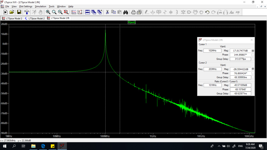
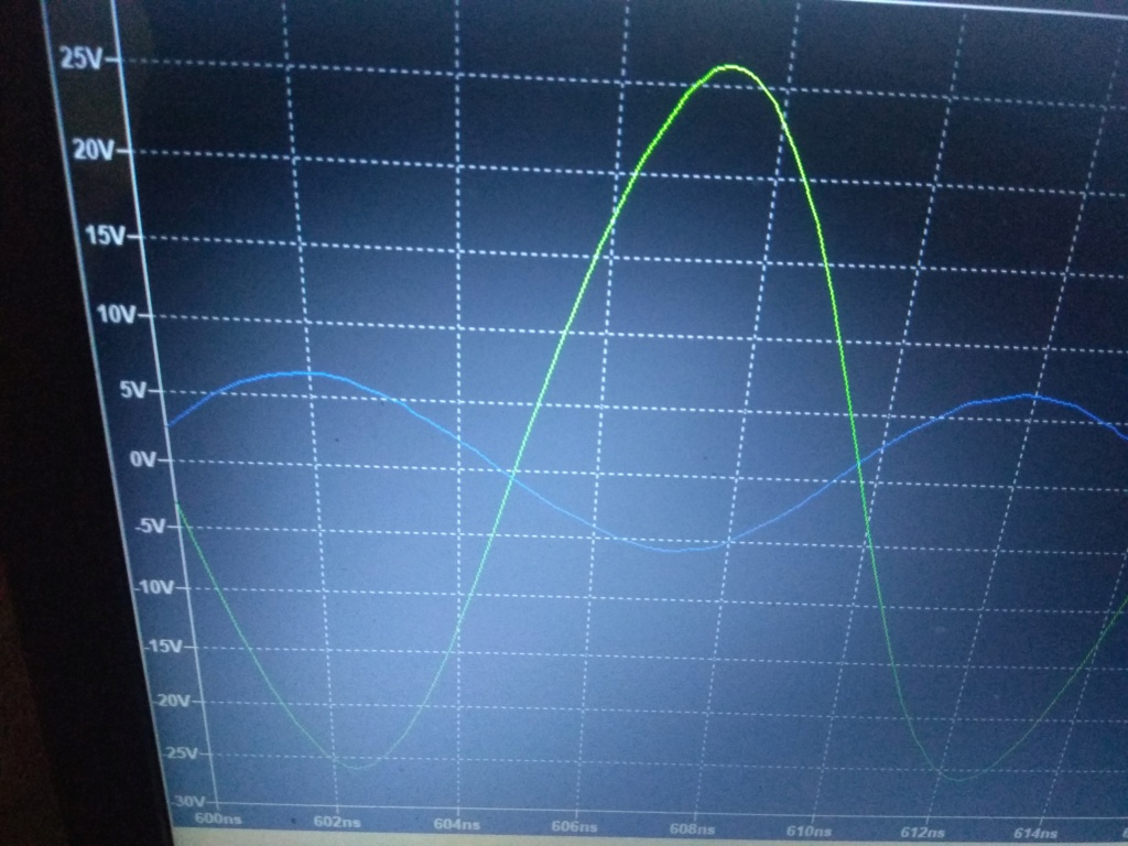
Clean output spectrum. 2nd harmonic is down > -40dBc.
dare4444- Posts : 427
Join date : 2013-03-19
2n7000 102MHz amp
![]() by dare4444 Fri Jul 24, 2020 7:48 pm
by dare4444 Fri Jul 24, 2020 7:48 pm
Last edited by dare4444 on Tue May 10, 2022 12:23 am; edited 10 times in total
dare4444- Posts : 427
Join date : 2013-03-19
admin likes this post
» 4W 96MHz Amplifier (2N7000/BS170) !!
» 2n7000 X 3 , Class E Part15 Transmitter Idea
|
|
|