The random wire antenna
3 posters


Re: The random wire antenna
![]() by Andrew Tue Nov 09, 2021 11:15 am
by Andrew Tue Nov 09, 2021 11:15 am
Ivan wrote:Hi,
thank you for the correction. I removed the now unnecessary posts.
IMHO most autotuners use the L topology with sets of fixed value coils and capacitors swithed by relays.
You're welcome, and sorry for the mistake; as for autotuners, I thought they used "T" topology, but then I'm probably wrong, all in all the "L" topology would allow using less components, so from a commercial standpoint it may be a better candidate
Andrew- Posts : 150
Join date : 2021-03-24
Age : 63
Location : Italy
Re: The random wire antenna
![]() by Ivan Thu Nov 04, 2021 7:10 am
by Ivan Thu Nov 04, 2021 7:10 am
Hi,
thank you for the correction. I removed the now unnecessary posts.
IMHO most autotuners use the L topology with sets of fixed value coils and capacitors swithed by relays.
73 Ivan
thank you for the correction. I removed the now unnecessary posts.
IMHO most autotuners use the L topology with sets of fixed value coils and capacitors swithed by relays.
73 Ivan
Ivan- Posts : 793
Join date : 2012-11-25
Age : 64
Location : Praha, Czechia
Re: The random wire antenna
![]() by Andrew Wed Nov 03, 2021 6:18 pm
by Andrew Wed Nov 03, 2021 6:18 pm
as for the capacitors, a 500/600 pF (max value, example) variable would be a good start, the additional caps may then be calculated to either (depending from serial/parallel switch settings) 1.5 and 2 or 2/3 and 1/3 then ok, that's just a coarse idea
[edit]
for QRO it would be a good idea to use a wide spaced air variable or a vacuum variable, the fixed ones should be "door knob" type (high voltage) and the coil should be wound with appropriate diameter wire
[edit]
for QRO it would be a good idea to use a wide spaced air variable or a vacuum variable, the fixed ones should be "door knob" type (high voltage) and the coil should be wound with appropriate diameter wire
Andrew- Posts : 150
Join date : 2021-03-24
Age : 63
Location : Italy
Re: The random wire antenna
![]() by Andrew Wed Nov 03, 2021 12:48 pm
by Andrew Wed Nov 03, 2021 12:48 pm
Forgot, by the way such an antenna will need a matching unit, a good and simple one which may fit is the "L" matching network, the following pic (original here https://postimg.cc/xkZWtx09) shows a coarse idea for such a matching unit
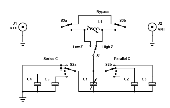
the circuit is classic, S1 allows to connect the tuning capacitor to either side of the coil, to allow matching Low or High impedances, S2 allows to insert additional fixed capacitors in series or in parallel with the variable one to cover a quite wide range of values, S3 is just the bypass switch; the coil L1 may either be a "roller coil" or a tapped one, in this latter case an additional rotary switch will be needed; the advantage of the "L" match is that it has only ONE "good" settings (as opposite to the "T" match which presents several "false" ones), has the lowest losses with respect to other matching networks ("PI", "T", ...) and, with proper design and properly chosen values for the inductor and capacitors, will be able to match a very wide range of impedances
By the way, the "L" match won't only be useful with the "random" but may also be effectively used with other antennas
Last edited by Andrew on Wed Nov 03, 2021 6:32 pm; edited 1 time in total
Andrew- Posts : 150
Join date : 2021-03-24
Age : 63
Location : Italy
Re: The random wire antenna
![]() by Andrew Tue Nov 02, 2021 12:45 pm
by Andrew Tue Nov 02, 2021 12:45 pm
Admin wrote:Hi Andrew,
That article really looks good. A lot of information. I also have a tree at the side of the (end of terrace) house and that could also be worth a try for the lower bands.
I have a load of QRM, probably from computer SMPSUs, that make the 160m and 80m bands unusable. 7m is noisy but usable. Now this tree I have is at the opposite side of the house to the neighbours so it could be worth a try to see if it still has the same noisy effects. Otherwise I will be going with the OtG loop antenna later on in the winter; I have already planned for that.
Thank you for sharing the information. Really appreciated.
Hi Harry, nice to read from you again, as for the antenna it isn't a beam, but despite being simple and cheap may offer decent performances; then it's far from being "quiet", but that can be solved by using a loop on ground for reception and a simple relay box to switch antennas on TX/RX
Oh and no need to thank, we're here to exchange and discuss ideas !
What else... oh yes, if you've a copy of 4NEC2 at hand, this is a model which will allow you to run some simulations so that you'll be able to see "what it does" and decide if it may be worth putting it up
- Code:
CM ===========================================
CM rand.nec - random wire antenna model
CM
CM length https://udel.edu/~mm/ham/randomWire/
CM
CM set characteristic impedance to 450, feed
CM with coax using a 9:1 UnUn followed by a
CM good 1:1 guanella choke both wound on #43
CM material toroids, FT240-43 will fit well
CM ===========================================
CE

' base values
SY freq=7.150                           ' initial test frequency
SY leng=26                              ' main antenna wire length
SY wire=0.00125                         ' wires radius
SY hfed=10                              ' feedpoint height
SY hend=5                               ' endpoint height
SY fwir=1                               ' feedpoint wire #
SY fseg=1                               ' feedpoint segment #
SY barm=3.5                             ' bottom arms length

' wire segmentation
SY segl=51                              ' segments for long wires
SY segs=11                              ' segments for short wires

' calculated values
SY hght=hfed                            ' feedpoint height
SY slpe=hend                            ' endpoint height
SY side=(hght-slpe)                     ' triangle vertical leg
SY endp=sqr((leng*leng)-(side*side))    ' endpoint distance
SY stub=slpe-1.5                        ' endpoint stub
SY cpse=hght-(wire*3.2)                 ' downwards counterpoise len
SY cplo=hght-cpse                       ' counterpoise bottom height


' main antenna wire
GW  1 segl    0   0   hght        endp                  0  slpe  wire

' vertical stub at far end
'GW  5 segs endp   0   slpe        endp                 0   stub  wire

' vertical counterpoise wire
GW 10 segs 0   0   cplo              0                 0   hght  wire

' bottom T section
GW 20 segs 0   0   cplo   (barm*sin(0))     (barm*cos(0))  cplo  wire
GW 21 segs 0   0   cplo (barm*sin(180))   (barm*cos(180))  cplo  wire

' fwd radials
'GW 22 segs 0   0   cplo  (barm*sin(45))    (barm*cos(45))  cplo  wire
'GW 23 segs 0   0   cplo  (barm*sin(90))    (barm*cos(90))  cplo  wire
'GW 24 segs 0   0   cplo (barm*sin(135))   (barm*cos(135))  cplo  wire

' aft radials
'GW 25 segs 0   0   cplo  (barm*sin(-45))  (barm*cos(-45))  cplo  wire
'GW 26 segs 0   0   cplo  (barm*sin(-90))  (barm*cos(-90))  cplo  wire
'GW 27 segs 0   0   cplo (barm*sin(-135)) (barm*cos(-135))  cplo  wire

' ground parameters
GE  -1
GN  2  0  0  0  13  0.005

' wires loading (copper)
LD  5   0  0  0  58000000

' feedpoint placement
EK
EX  0 fwir fseg 0 1 0 0

' initial test frequency
FR  0  1  0  0  freq  0

' end of model
EN
[edit]
In case of interest, a friend from Greece (Kostas, SV3ORA) has built a "random" antenna following my directions and he has been using it for months with good results, the infos about the Kostas build can be found here http://qrp.gr/randomwireant/index.htm notice that instead of the suggested 9:1 UnUn he decided to build a "multi tap" one
Last edited by Andrew on Wed Nov 03, 2021 12:50 pm; edited 1 time in total
Andrew- Posts : 150
Join date : 2021-03-24
Age : 63
Location : Italy
Re: The random wire antenna
![]() by admin Tue Nov 02, 2021 12:31 pm
by admin Tue Nov 02, 2021 12:31 pm
Hi Andrew,
That article really looks good. A lot of information. I also have a tree at the side of the (end of terrace) house and that could also be worth a try for the lower bands.
I have a load of QRM, probably from computer SMPSUs, that make the 160m and 80m bands unusable. 7m is noisy but usable. Now this tree I have is at the opposite side of the house to the neighbours so it could be worth a try to see if it still has the same noisy effects. Otherwise I will be going with the OtG loop antenna later on in the winter; I have already planned for that.
Thank you for sharing the information. Really appreciated.
BR Harry - SM0VPO
_________________
Everything in this world is either bacon, or it isn't bacon
They say that money cannot bring you happiness, but if you have it then you can always buy more bacon

admin- Admin
- Posts : 1144
Join date : 2012-11-24
Age : 72
Location : Märsta, Sweden -

The random wire antenna
![]() by Andrew Sun Oct 31, 2021 5:12 pm
by Andrew Sun Oct 31, 2021 5:12 pm
Given that there's some interest, here are some infos from my experience which may hopefully be of help setting up such an often undervalued antenna
What follows is a way of installing the random without using a remote tuner and still using a run of coax to feed it instead of bringing the. antenna wire (and its RADIATION) inside the shack
First of all, on the contrary of most designs found on the net, I prefer installing the antenna as high and "in the clear" as possible, also, keeping both antenna ends a far enough (say 25 to 50 cm) from supports; the main antenna wire may then run horizontally or slightly sloping from the feedpoint
That said, the first step is finding a lenght which fits your available space, such a lenght is far from being "random" since, to allow tuning the antenna on the ham bands, we'll need to stay away from 1/4 wave (low impedance) and 1/2 wave (high impedance) and multiples on all bands where we want to use our antenna, plus, we'll also want the antenna to be near/longer to 1/4 wave at the lower frequency we want to use it on; now, to ease finding a lenght we may refer to the chart found here
https://udel.edu/~mm/ham/randomWire/
just pick the longest "good" lenght which fits your available space, at that point you'll need some other things, the first is the so called counterpoise, it's a piece of wire completing the missing half of your "random" and it's NEEDED, do not believe to the ones saying that it is unneeded, w/o a counterpoise an endfed will use WHATEVER is connected to its end, which means the coax and everything connected to it, so... we'll WANT a counterpoise, the latter will just be a run of wire dropping down to ground, there it may be connected to some radials or just laid out on ground
at the feedpoint we'll use a 9:1 UnUn, there's no magic in that, it's just a way to bring the antenna impedance down to a value which will be more or less around the one of the coax, so minimizing losses and allowing the ATU in the shack to easily find a match, the UnUn can be easily build, start from the informations found here
http://vk6ysf.com/unun_9-1_v2.htm
but use an FT240-43 toroid and wind 10 or 11 trifilar turns (as for the above link), the resulting UnUn will serve you well on the whole HF range with power up to at least 400W (probably more, but I tend to be conservative); now that we transformed the impedance, we'll also need another bit to "convince" our antenna to use the counterpoise as its "missing half"; so we'll need a choke, to wind it, follow this design
http://vk6ysf.com/balun_guanella_current_1-1.htm
but, again, wind it using a piece of RG174 coax and making a total of 17 turns (8+bypass+ the reason is explained here
http://www.karinya.net/g3txq/chokes/
my suggestion is, if possible, to build two of those chokes and place the first after the UnUn and the second immediately before the coax, feeding the antenna, enters your building to reach the shack
With this setup most ATU won't have problems in finding a match and you won't have issues with "RF in the shack"
Just a final note, use a pulley and a weight for either or both ropes supporting the antenna wire, this way, if ice or wind will load the wire of if a tree branch will fall over it, the pulley will allow the rope to slide, relieving the load and avoiding breaks
the above being said, let me make an example, if we follow the above directions and put up an antenna with the feedpoint at 10m from ground, the far end at 5 meters from ground a total lenght of 26 metes and a counterpoise running vertically from the feedpoind (unun gnd) to ground, and connected there to a couple of 3.5 meters wires forming an inverted T, we'll have an antenna which will allow us to get on the air on all bands from 80 to 10 meters, an example of such an antenna can be seen here (NEC model)
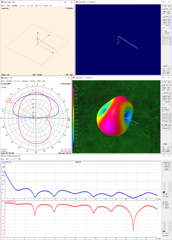
as you can see, the radiation pattern isn't bad and the SWR curve can be easily matched using a regular ATU; sure, on 80 the performance won't be great, but sufficient for local QSOs, then from 40 and up to 10 the antenna may offer some surprising results
What follows is a way of installing the random without using a remote tuner and still using a run of coax to feed it instead of bringing the. antenna wire (and its RADIATION) inside the shack
First of all, on the contrary of most designs found on the net, I prefer installing the antenna as high and "in the clear" as possible, also, keeping both antenna ends a far enough (say 25 to 50 cm) from supports; the main antenna wire may then run horizontally or slightly sloping from the feedpoint
That said, the first step is finding a lenght which fits your available space, such a lenght is far from being "random" since, to allow tuning the antenna on the ham bands, we'll need to stay away from 1/4 wave (low impedance) and 1/2 wave (high impedance) and multiples on all bands where we want to use our antenna, plus, we'll also want the antenna to be near/longer to 1/4 wave at the lower frequency we want to use it on; now, to ease finding a lenght we may refer to the chart found here
https://udel.edu/~mm/ham/randomWire/
just pick the longest "good" lenght which fits your available space, at that point you'll need some other things, the first is the so called counterpoise, it's a piece of wire completing the missing half of your "random" and it's NEEDED, do not believe to the ones saying that it is unneeded, w/o a counterpoise an endfed will use WHATEVER is connected to its end, which means the coax and everything connected to it, so... we'll WANT a counterpoise, the latter will just be a run of wire dropping down to ground, there it may be connected to some radials or just laid out on ground
at the feedpoint we'll use a 9:1 UnUn, there's no magic in that, it's just a way to bring the antenna impedance down to a value which will be more or less around the one of the coax, so minimizing losses and allowing the ATU in the shack to easily find a match, the UnUn can be easily build, start from the informations found here
http://vk6ysf.com/unun_9-1_v2.htm
but use an FT240-43 toroid and wind 10 or 11 trifilar turns (as for the above link), the resulting UnUn will serve you well on the whole HF range with power up to at least 400W (probably more, but I tend to be conservative); now that we transformed the impedance, we'll also need another bit to "convince" our antenna to use the counterpoise as its "missing half"; so we'll need a choke, to wind it, follow this design
http://vk6ysf.com/balun_guanella_current_1-1.htm
but, again, wind it using a piece of RG174 coax and making a total of 17 turns (8+bypass+
http://www.karinya.net/g3txq/chokes/
my suggestion is, if possible, to build two of those chokes and place the first after the UnUn and the second immediately before the coax, feeding the antenna, enters your building to reach the shack
With this setup most ATU won't have problems in finding a match and you won't have issues with "RF in the shack"
Just a final note, use a pulley and a weight for either or both ropes supporting the antenna wire, this way, if ice or wind will load the wire of if a tree branch will fall over it, the pulley will allow the rope to slide, relieving the load and avoiding breaks
the above being said, let me make an example, if we follow the above directions and put up an antenna with the feedpoint at 10m from ground, the far end at 5 meters from ground a total lenght of 26 metes and a counterpoise running vertically from the feedpoind (unun gnd) to ground, and connected there to a couple of 3.5 meters wires forming an inverted T, we'll have an antenna which will allow us to get on the air on all bands from 80 to 10 meters, an example of such an antenna can be seen here (NEC model)
as you can see, the radiation pattern isn't bad and the SWR curve can be easily matched using a regular ATU; sure, on 80 the performance won't be great, but sufficient for local QSOs, then from 40 and up to 10 the antenna may offer some surprising results
Last edited by Andrew on Tue Nov 02, 2021 12:09 pm; edited 1 time in total (Reason for editing : Added image)
Andrew- Posts : 150
Join date : 2021-03-24
Age : 63
Location : Italy
Densil likes this post
» End fed wire antenna + coaxial transformer
» The LoG antenna
» antenna 80m
» The "Fat Max" antenna
» V Pole antenna
» The LoG antenna
» antenna 80m
» The "Fat Max" antenna
» V Pole antenna
Permissions in this forum:
You can reply to topics in this forum|
|
|