Interesting/unusual oscillator circuit
4 posters


Interesting/unusual oscillator circuit
![]() by John_1981 Mon Nov 22, 2021 10:08 pm
by John_1981 Mon Nov 22, 2021 10:08 pm
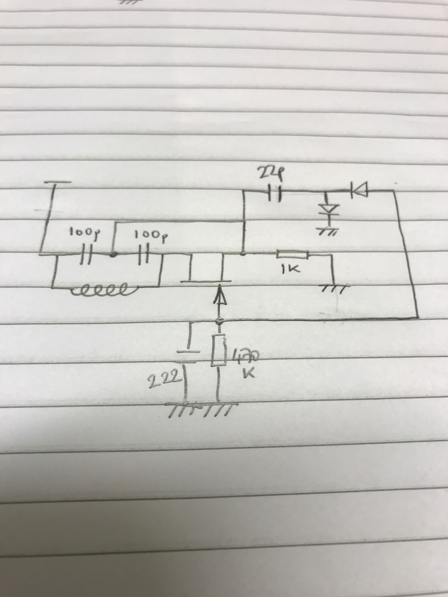
Another LC oscillator with amplitude stabilisation. The diodes rectify a sample of the oscillator output and develop an increasingly negative bias to the FET gate with increasing amplitude. This circuit gives a clean output at the source terminal of the FET, some other configurations I tried give a clean waveform across the tank circuit but not where I would like to couple the output from. This gives 3V P-P across the 1k source resistor.
John_1981- Posts : 32
Join date : 2021-11-07
admin likes this post
Interesting/unusual oscillator circuit
![]() by John_1981 Wed Nov 10, 2021 10:31 pm
by John_1981 Wed Nov 10, 2021 10:31 pm

AGC/Level control added to VHF colpitts type oscillator. The circuit is not optimised, but the output level is held at a constant 8V P-P from 430-860kHz.
John_1981- Posts : 32
Join date : 2021-11-07
admin likes this post
Interesting/unusual oscillator circuit
![]() by John_1981 Wed Nov 10, 2021 9:49 pm
by John_1981 Wed Nov 10, 2021 9:49 pm
Glenndk,
I stumbled across this site last night with lots of info on negative resistance oscillators, with lots of info on how to make up a negative resistance circuit using garden variety BJTs. Unfortunately I do not have any P-channel FETS as used in the usual Lambda diode circuit:
https://sites.google.com/site/linuxdigitallab/low-noise-crystal-experiment/vco-negative-resistance-vco
Harry,
I have seen the circuit using the C/E junction backwards in reverse breakdown mode as the basis of an LED flasher but never thought of trying it in an RF oscillator. I did get a nice sawtooth out of a VR150 years ago whilst playing with valves.
Not sure about frequency change with temperature, as i'm planning on using this as a VCO in a PLL scheme i don't care too much about drift at the moment. That said, the two transistor oscillator works at very low power level (0.6-1.0V and only microamps) so self heating of the active devices should be minimal.
After encouraging results with negative feedback applied to more conventional circuits, i will explore this more for the time being. If the negative feedback resistor is replaced with a FET I have a voltage controlled resistor, so this may be useful as the basis of an AGC system to prevent clipping of the RF waveform. I experimented with something similar for an IF amplifier where the emitter bypass capacitor was connected to ground via a FET and the gate voltage varied to control emitter degeneration in the amplifier.
John_1981- Posts : 32
Join date : 2021-11-07
admin likes this post
Re: Interesting/unusual oscillator circuit
![]() by Glenndk Wed Nov 10, 2021 11:24 am
by Glenndk Wed Nov 10, 2021 11:24 am
John_1981 wrote:Image posting test
https://pbs.twimg.com/media/FDyP9vpX0AQLuzF?format=jpg&name=4096x4096
Thanks for showing your oscillator.
_________________
best regards,
Glenn / OZ1HFT
Glenndk- Posts : 114
Join date : 2017-01-06
Location : Copenhagen, Denmark -

admin likes this post
Re: Interesting/unusual oscillator circuit
![]() by admin Wed Nov 10, 2021 9:06 am
by admin Wed Nov 10, 2021 9:06 am
Hello John,
Thank you for posting and sharing this information. I have done a lot of work using negative resistance oscillators. The first was back in the 70's when there were many tunnel-diodes, such as the AEY11. I now have a heap or Russian NOS TDs. I use one of them to measure cable lengths - clank the TD across the end of a roll of coaxial cable (used as a resonator) and measure the frequency.
I read in an old Practical Wireless issue around 1985 that a simple BC547/2N2222 can be used used to make a NR oscillator, and this I have used from 75Hz to about 10MHz. Many people have published articles using the same configuration:

The disadvantage with this is that a TD can "hoot" with a single 1.5V cell, but the NDR above needs to have about 12V. If you omit the inductor L1 (short-circuit it) then it works very well down to just a few Hz as some a of relaxation oscillator. In this event you have to be careful with the capacitor discharge current, which can be quite high.
I have also use neon tubes, the type you get in "mains tester" screwdrivers and the starters for fluorescent tubes. One high-value resistor from over 120V and a cap across the tube and it also oscillates beautifully. An easy way to get a ramp waveform for a cheap oscilloscope. I nevert tried this for RF, but the BC547/2N2222 works well.
These circuits do not have any level control, and the BC547/2N2222 seem to be rather stable due to the higher supply voltage.
The circuit you posted using two PNP transistors I saw many years ago, but unlike you I did not follow it up. Your description and pictures are really good. You have done a lot with this. I particularly liked the ALC to stabilize the output level. It the time-constant of the NFB is chosen wisely then it will probably remove supply ripple. I read your description with great interest.
Do you get any frequency changes when the two PNP devices suffer a temperature change? I saw this using the tunnel-diodes, but instead of clanking the negative-resistance across the tuned circuit, it works well connecting it to a tapping of the coil, where the device capacitance (changes) have little effect.
I have followed all the links that were posted to this thread, including the NDR thread a few years ago.
So thank you for starting this thread. This sort of thing I really love to read about and play with, sometimes in unusual ways
Very best regards from Harry - SM0VPO
Thank you for posting and sharing this information. I have done a lot of work using negative resistance oscillators. The first was back in the 70's when there were many tunnel-diodes, such as the AEY11. I now have a heap or Russian NOS TDs. I use one of them to measure cable lengths - clank the TD across the end of a roll of coaxial cable (used as a resonator) and measure the frequency.
I read in an old Practical Wireless issue around 1985 that a simple BC547/2N2222 can be used used to make a NR oscillator, and this I have used from 75Hz to about 10MHz. Many people have published articles using the same configuration:
The disadvantage with this is that a TD can "hoot" with a single 1.5V cell, but the NDR above needs to have about 12V. If you omit the inductor L1 (short-circuit it) then it works very well down to just a few Hz as some a of relaxation oscillator. In this event you have to be careful with the capacitor discharge current, which can be quite high.
I have also use neon tubes, the type you get in "mains tester" screwdrivers and the starters for fluorescent tubes. One high-value resistor from over 120V and a cap across the tube and it also oscillates beautifully. An easy way to get a ramp waveform for a cheap oscilloscope. I nevert tried this for RF, but the BC547/2N2222 works well.
These circuits do not have any level control, and the BC547/2N2222 seem to be rather stable due to the higher supply voltage.
The circuit you posted using two PNP transistors I saw many years ago, but unlike you I did not follow it up. Your description and pictures are really good. You have done a lot with this. I particularly liked the ALC to stabilize the output level. It the time-constant of the NFB is chosen wisely then it will probably remove supply ripple. I read your description with great interest.
Do you get any frequency changes when the two PNP devices suffer a temperature change? I saw this using the tunnel-diodes, but instead of clanking the negative-resistance across the tuned circuit, it works well connecting it to a tapping of the coil, where the device capacitance (changes) have little effect.
I have followed all the links that were posted to this thread, including the NDR thread a few years ago.
So thank you for starting this thread. This sort of thing I really love to read about and play with, sometimes in unusual ways
Very best regards from Harry - SM0VPO
_________________
Everything in this world is either bacon, or it isn't bacon
They say that money cannot bring you happiness, but if you have it then you can always buy more bacon

admin- Admin
- Posts : 1144
Join date : 2012-11-24
Age : 72
Location : Märsta, Sweden -

John_1981- Posts : 32
Join date : 2021-11-07
admin likes this post
Interesting/unusual oscillator circuit
![]() by John_1981 Mon Nov 08, 2021 11:17 pm
by John_1981 Mon Nov 08, 2021 11:17 pm
"Quote: "...
In this circuit the parasitic oscillations can arise, in this case increase slightly the resistance of the resistor R2 to suppress them.
..."
Have you experienced these parasitic oscillations?
No, I have not experienced any parasitic oscillations, perhaps if I used 'hotter' transistors than BC556's I may have problems. I tried substituting the LC network with a resistor, capacitor and parallel RC circuit and could not get it to oscillate. Initially I used a short for R2 as it was listed as 10 ohms I didn't think it would do much. I tried a few resistors in this position (100, 150, 470R and 2k7), the amplitude drops but other than that it doesn't make much difference. With 2.7K the oscillator does not start but will maintain oscillation if R2 is temporarily shorted. I suspect this resistor introduces a little negative feedback.
The two transistors might constitute an unknown/unnamed negative resistance circuit/critically tuned Q-multipler? I have no other explaination. I can see that the two transistors V1, V2 constitute an amplifier with 360 degree phase change, whose input and output has been connected together. It could be interesting to draw a graph of the negative resistance curve. What does it look like (must have negative slope on part of the graph)? Line like? How does the AGC V6-current/voltage change the graph?
To me the circuit reminds me of a Franklin oscillator where 2 active devices each produce 180 deg. phase shift to give an overall shift of 0/360 deg. Unfortunately I do not have a curve tracer to investigate further, but a negative resistance oscillator should be able to work with an RC circuit; this does not or I am not trying hard enough.
For the AGC I connected the output of the rectifier/input to V7 base to the - input of a CA3140 and a LED reference voltage of about 1.4V to the +input. Op amp output to the common emitters of V1/V2 via a 15K resistor. As the current draw is so small the op amp doesnt need buffering. The AGC seemed to work OK but didn't investigate it further.
For my purposes I think AGC is unnecessary as I can get a clean sine wave over a wide frequency range by altering the values of R1, R2 or even by shunting a damping resistor across the LC circuit.
If V1, V2 constitute a negative resistance circuit, then it could be interesting to decoupled V1,V2-emitters with a capacitor to common? The current through V6 might drop some? The V6 emitter has low LF-impedance; but might have higher HF-impedance and that might dampen the V1,V2-negative resistance? (Adding the capacitor might make the AGC-loop unstable?):
Decoupling the common emitters of V1/V2 with either a 0.1uF or 2200pF capacitor reduces the output of the oscillator. To me this should be similar to the common emitter node on a long tailed pair where equal and opposite phase voltages cancel out.
With C4/0.22uF in circuit the circuit was unstable. I have nightmares about control loop stabilisation from my experiments with PLL circuits.
All in all, I'm still impressed by the clean waveform, simplicity of the circuit and wide tuning range of this circuit. So far its done 0.5Hz-8.5MHz.
John_1981- Posts : 32
Join date : 2021-11-07
admin likes this post
Re: Interesting/unusual oscillator circuit
![]() by Glenndk Mon Nov 08, 2021 12:11 pm
by Glenndk Mon Nov 08, 2021 12:11 pm
John_1981 wrote:The circuit diagram is at http://zpostbox.ru/universal_lc_oscillator.htm.
This link works - interesting circuit:
http://zpostbox.ru/universal_lc_oscillator.html
Quote: "...
In this circuit the parasitic oscillations can arise, in this case increase slightly the resistance of the resistor R2 to suppress them.
..."
Have you experienced these parasitic oscillations?
The two transistors might constitute an unknown/unnamed negative resistance circuit/critically tuned Q-multipler? I have no other explaination. I can see that the two transistors V1, V2 constitute an amplifier with 360 degree phase change, whose input and output has been connected together. It could be interesting to draw a graph of the negative resistance curve. What does it look like (must have negative slope on part of the graph)? Line like? How does the AGC V6-current/voltage change the graph?
If V1, V2 constitute a negative resistance circuit, then it could be interesting to decoupled V1,V2-emitters with a capacitor to common? The current through V6 might drop some? The V6 emitter has low LF-impedance; but might have higher HF-impedance and that might dampen the V1,V2-negative resistance? (Adding the capacitor might make the AGC-loop unstable?)
.
Compare with:
https://web.archive.org/web/20210226040626/http://users.tpg.com.au/users/ldbutler/NegResDipMeter.htm
https://web.archive.org/web/20191025210540/http://www.keelynet.com/zpe/negistor.htm
http://www.vk6fh.com/vk6fh/lambda_diode.htm
From:
https://sm0vpo.forumotion.com/t165-ndr-oscillators-has-anyone-experimented-with-them#837
https://sm0vpo.forumotion.com/t165-ndr-oscillators-has-anyone-experimented-with-them#857
More:
https://sm0vpo.forumotion.com/t165-ndr-oscillators-has-anyone-experimented-with-them#839
https://en.wikipedia.org/wiki/Q_multiplier
-
If you are bored now, then look at this chaos oscillator:
https://sm0vpo.forumotion.com/t178-tunnel-diode-interesting-i-e-useless-experiments#896
_________________
best regards,
Glenn / OZ1HFT
Glenndk- Posts : 114
Join date : 2017-01-06
Location : Copenhagen, Denmark -
admin likes this post
Interesting/unusual oscillator circuit
![]() by John_1981 Mon Nov 08, 2021 11:56 am
by John_1981 Mon Nov 08, 2021 11:56 am
The circuit diagram is at http://zpostbox.ru/universal_lc_oscillator.htm. I omitted the AGC circuit initially, then used an op amp in place of V7 and V6.

John_1981- Posts : 32
Join date : 2021-11-07
admin likes this post
Re: Interesting/unusual oscillator circuit
![]() by john_1981 Fri Nov 05, 2021 10:29 am
by john_1981 Fri Nov 05, 2021 10:29 am
Glennddk,
Thanks for those useful links, I will take some time to browse through those oscillator circuits, although for the time being I am going to do some further investigation with the circuit I have been working on. I'm sure at some stage it will become apparent that the simplicity will come at some disadvantage...
Thanks for those useful links, I will take some time to browse through those oscillator circuits, although for the time being I am going to do some further investigation with the circuit I have been working on. I'm sure at some stage it will become apparent that the simplicity will come at some disadvantage...
john_1981- Guest
Re: Interesting/unusual oscillator circuit
![]() by john_1981 Fri Nov 05, 2021 10:26 am
by john_1981 Fri Nov 05, 2021 10:26 am
"The schematic can be redrawn with more common NPN transistors. Simply interchange the V+ and V-. Does the oscillator work with silicon transistors, or old germanium ones must be used?"
Yes the circuit could be turned upside down and replaced with NPN devices, but I prefer having the LC tank circuit referenced to GND rather than +V.
I used silicon transistors, a pair of BC556's. I tried some different coil/capacitor combinations and just for fun I tried a mains transformer winding and 4.7uF capacitor. The circuit oscillated at around 0.5Hz.
The circuit still oscillates with a supply voltage down to about 0.5V
john_1981- Guest
Re: Interesting/unusual oscillator circuit
![]() by Glenndk Fri Nov 05, 2021 8:44 am
by Glenndk Fri Nov 05, 2021 8:44 am
John_1981 wrote:Hi all,
...In the quest for a decent VCO I have been trying different oscillator configurations (CE colpitts, CB colpitts, hartley, various jfet circuits, etc.) but have not been happy with the amount of distortion on the output.
...
Advantages for me are wide tuning range, sinusoidal output, lack of fussiness, low current consumption and no need for a capacitive/inductive tap.
...
Hi John
You should definitely read this post:
https://sm0vpo.forumotion.com/t309-old-radio-circuits#1868
Especially:
Frequency compensated LC networks for oscillators with the wide tuning range.
by Vladimir Novichkov
02/01/2012 rev 0.43
http://www.kearman.com/vladn/hybrid_feedback.pdf
backup:
https://web.archive.org/web/20161022044737/http://www.kearman.com/vladn/hybrid_feedback.pdf
(Paper page 24: "Test prototype 2.")
and this paper:
Tesla Technical reports:
December 1949, Jiri Vackar [Jiří Vackář], LC oscillators and their frequency stability:
http://web.archive.org/web/20120219062848/n1ekv.org/Oscillators/Vackar_wholepaper.pdf
( http://n1ekv.org/Oscillators/Vackar_wholepaper.pdf )
The Vackar VFO oscillator:
http://www.qsl.net/va3diw/vackar.html
backup:
https://web.archive.org/web/20200207214215/https://www.qsl.net/va3diw/vackar.html
Quote: "...
Jiri Vackar [Jiří Vackář], (correctly pronounced as "Vatzkaarz")
invented his VFO oscillator during late 40s. It is probably the most stable VFO oscillator known. Thanks George!
The Vackar oscillator configuration is rarely used because of known reason. ( NIH, the not-invented-here syndrome ).
The frequency tuning range is above 2.5, not observable in any other type of oscillator. The Coupling ratio is fixed; typical range is 1:4 up to 1:9. The frequency tuning is provided independently of coupling. Transistor's parametric variables are isolated from the resonator. The transistor input is not overloaded as Clapp or other circuits. The collector output is at low impedance providing low gain just to maintain the oscillation. The feedback division ratio is fixed. Even if the VFO is tuned, the impedance divider is fixed. The stability is close to XO - crystal oscillator. Jiri Vackar published his work in a book, providing theory and analysis of each type of his oscillator.
..."
_________________
best regards,
Glenn / OZ1HFT
Glenndk- Posts : 114
Join date : 2017-01-06
Location : Copenhagen, Denmark -
Re: Interesting/unusual oscillator circuit
![]() by Ivan Fri Nov 05, 2021 5:36 am
by Ivan Fri Nov 05, 2021 5:36 am
Hi John,
you probably cannot post pitures while you have the guest status. Ask Harry for granting you a full membersip to this forum.
The circuits is interesting. It ressembles me an UJT oscillator (UJT = unijunction transistor, which was often replaced by a complementary pair of common bipolar transistors). I have seen an Xtal tester in similar configuration, too. If you use a varicap in the LC circuit, you will get a simple and reliable VCO!
The schematic can be redrawn with more common NPN transistors. Simply interchange the V+ and V-. Does the oscillator work with silicon transistors, or old germanium ones must be used?
VBR from Ivan
Ivan- Posts : 793
Join date : 2012-11-25
Age : 64
Location : Praha, Czechia
admin likes this post
Interesting/unusual oscillator circuit
![]() by John_1981 Thu Nov 04, 2021 10:48 pm
by John_1981 Thu Nov 04, 2021 10:48 pm
Hi all,
In relation to my recent work on frequency synthesizers, In the quest for a decent VCO I have been trying different oscillator configurations (CE colpitts, CB colpitts, hartley, various jfet circuits, etc.) but have not been happy with the amount of distortion on the output.
I have come across this circuit. Apologies for the wordy description, I'm not sure how to post a schematic:
2x PNP transistors. Emitters tied together then to +v via a resistor. Im using 10K but it still oscillates with 47k, may be able to go even higher. Base of Tr1 strapped to collector of Tr2. Base of Tr2 strapped to collector of Tr1 and to -V. LC tank circuit between the junction of Tr1 B, Tr2 C and -V.
By adjusting the +V supply, I get a nice looking sinusoidal output and the oscillator doesn't seem at all fussy about L/C ratios. With a red oscillator coil from a scrap AM transistor radio, It still oscillated with 1000pF across it. Other configurations gave up with more than 100pF.
The circuit works best with a low supply voltage around 1.5V so a red LED (painted black if necessary to stop it being light sensitive) may be suitable to use as a shunt regulator. I assume it must be some kind of negative resistance oscillator, so I would expect the output frequency to vary with the supply voltage.
Advantages for me are wide tuning range, sinusoidal output, lack of fussiness, low current consumption and no need for a capacitive/inductive tap.
John_1981- Guest
» tunable Xtal oscillator circuit
» Interesting development - spectrum analysers
» Interesting bit of information
» Unusual experiment - "fairy-lights" antenna. Can you beat that?
» interesting radio thing
» Interesting development - spectrum analysers
» Interesting bit of information
» Unusual experiment - "fairy-lights" antenna. Can you beat that?
» interesting radio thing
Permissions in this forum:
You can reply to topics in this forum