FM Transmitter V8


Re: FM Transmitter V8
![]() by dare4444 Sat Dec 17, 2022 8:48 am
by dare4444 Sat Dec 17, 2022 8:48 am
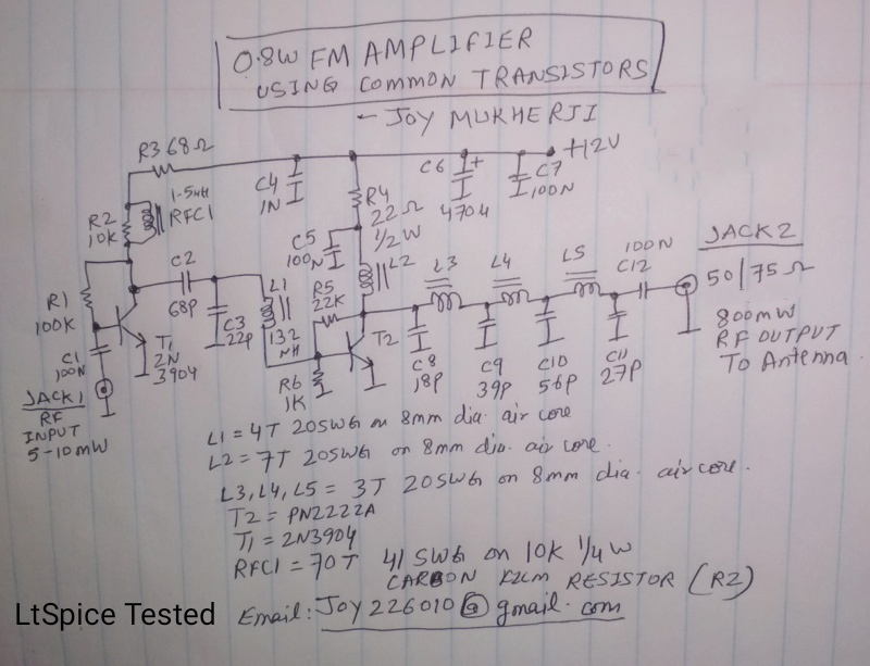
My mistake, Ruud. Thanks for pointing out the error. It was an initial mistake in calculation.Ruud wrote:I was looking at the hand drawn schamatic with the 'stereo' input.
I suppose that the 10K/500 nF combination was intended to work as a pre-emphasis network?
This would give a time constant of
(500 x 10-9) x (10 x 103) or 5000 µS.
Isn't that a bit too much, where 50 µS (or 75 µS for other countries) is expected?
(With a load impedance around 4.7 K.ohm it won't work properly anyway, but I think this R-C combination is something to think about...
dare4444- Posts : 427
Join date : 2013-03-19
Re: FM Transmitter V8
![]() by Ruud Sun Dec 11, 2022 8:14 pm
by Ruud Sun Dec 11, 2022 8:14 pm
I suppose that the 10K/500 nF combination was intended to work as a pre-emphasis network?
This would give a time constant of
(500 x 10-9) x (10 x 103) or 5000 µS.
Isn't that a bit too much, where 50 µS (or 75 µS for other countries) is expected?
(With a load impedance around 4.7 K.ohm it won't work properly anyway, but I think this R-C combination is something to think about...

Ruud- Posts : 130
Join date : 2012-11-26
Age : 68
Location : Haule, The Netherlands -

Re: FM Transmitter V8
![]() by dare4444 Sun Nov 06, 2022 10:26 am
by dare4444 Sun Nov 06, 2022 10:26 am
dare4444 wrote:sm0vpo wrote:
I wonder if Joy has experienced another effect?
I think I found it.
The amplifier chain must have been overdriven without the 100ohm series resistor. Makes sense?
dare4444- Posts : 427
Join date : 2013-03-19
Re: FM Transmitter V8
![]() by dare4444 Mon Sep 26, 2022 10:39 pm
by dare4444 Mon Sep 26, 2022 10:39 pm
dare4444- Posts : 427
Join date : 2013-03-19
Re: FM Transmitter V8
![]() by dare4444 Mon Sep 26, 2022 10:16 pm
by dare4444 Mon Sep 26, 2022 10:16 pm
sm0vpo wrote:
I wonder if Joy has experienced another effect?
You are my teacher. Nothing that I do is my own work. V8 is an amazing circuit, 180mW is sufficient to produce 12W output with most VHF power mosfets. I am not sure why removing the 100ohm resistor introduced audio distortion slightly, no clue, and it remains one of my unanswered questions. The rest you've answered them over the years. I've never learned so much from any website or any book. Your site and online presence is really unique, and I'm sure you've inspired many others as well with your unique approach to RF design techniques.
Regards,
Joy
dare4444- Posts : 427
Join date : 2013-03-19
sm0vpo likes this post
Re: FM Transmitter V8
![]() by sm0vpo Mon Sep 26, 2022 4:30 pm
by sm0vpo Mon Sep 26, 2022 4:30 pm
Ruud wrote:Personally I never found that the distortion was depending on the output level of an oscillator.
The varicap circuit should be completely isolated and not be influenced by the HF level.
An exception could be if the HF voltage over the varicap is so high, that the varicap starts conducting.
Hello Ruud,
When I designed this I figured that I could:
1 - use a standalone oscillator for lower powers (it was to be VCO in a synth)
2 - use TR2 as a buffer, but ...
TR2 base current will be small compared to the current availability from TR1, less than 0.5mA (hfe >100). I figured that this would be a small load percentage of the available current, improving the buffer effect on the oscillator.
But Joy has done a LOT of work with FM transmitters and I am open to any and all new information based on experiences.
The oscillator voltage at the Base of TR1 is around 2v RMS. The varicap is biased at 3V DC (can go up to 9V). This means that a 16V Zener used as a varicap will not hit the avalanch point. I also have quite a wide RF range from the tuning voltage for use as a synthesiser, so the non-linear voltage/frequency characteristic of the Zener/varicap should be very small due to the modulation sensitivity.
I wonder if Joy has experienced another effect? I know that I am learning with every project. Sometimes things do not work as planned, but in this case everything fitted together seemingly perfectly.
The only improvement for the future is to space out the circuit a bit more and use a much bigger ground-plane. The V8 is relatively small and I can "sniff" RF on the ground-copper around the board. Next time there will be a lot more copper, or ideally a double-sided board.
Very best regards from Harry - sm0vpo
sm0vpo- Admin
- Posts : 110
Join date : 2013-03-26
Age : 72
Location : Märsta, Sweden
Re: FM Transmitter V8
![]() by dare4444 Mon Sep 26, 2022 3:50 pm
by dare4444 Mon Sep 26, 2022 3:50 pm
Ruud wrote:That is even stranger, because emitter follower T2 is supposed to isolate the oscillator from any further load.
Ft is 350MHz for 2N3904. I'm not sure how much isolation is it gonna provide. The same audio distortion was noted in another circuit built in 2013. 100ohm R7 took care of the problem.
dare4444- Posts : 427
Join date : 2013-03-19
Re: FM Transmitter V8
![]() by Ruud Mon Sep 26, 2022 2:17 pm
by Ruud Mon Sep 26, 2022 2:17 pm
Ruud- Posts : 130
Join date : 2012-11-26
Age : 68
Location : Haule, The Netherlands -
sm0vpo likes this post
Re: FM Transmitter V8
![]() by dare4444 Mon Sep 26, 2022 1:54 pm
by dare4444 Mon Sep 26, 2022 1:54 pm
Ruud wrote:Personally I never found that the distortion was depending on the output level of an oscillator.
The varicap circuit should be completely isolated and not be influenced by the HF level.
An exception could be if the HF voltage over the varicap is so high, that the varicap starts conducting.
Lowering R11 resulted in audio distortion. I never quite understood why? And R4 should be replaced by a 100uH choke and a series 2.2K resistor right for better stereo audio?
dare4444- Posts : 427
Join date : 2013-03-19
sm0vpo likes this post
Re: FM Transmitter V8
![]() by Ruud Mon Sep 26, 2022 12:50 pm
by Ruud Mon Sep 26, 2022 12:50 pm
The varicap circuit should be completely isolated and not be influenced by the HF level.
An exception could be if the HF voltage over the varicap is so high, that the varicap starts conducting.
Ruud- Posts : 130
Join date : 2012-11-26
Age : 68
Location : Haule, The Netherlands -
sm0vpo likes this post
Re: FM Transmitter V8
![]() by sm0vpo Mon Sep 26, 2022 12:42 pm
by sm0vpo Mon Sep 26, 2022 12:42 pm
Yes, I have done some listening tests and I also did some oscilloscope checks for frequency response, and the recovered audio was identical to the input, as far as my ears could tell.
On the oscilloscope the audio waveform (from sine generator) is not at all distorted with full 150kHz deviation (+/-75).
The low frequency response is also just a few Hz, perfect for disco and synth. The upper frequency response was limited by the receiver, but according to the analyser it far exceed 200kHz. I have to add AF filtering. As I wrote below, my MP3 audio source also has a 256kHz tone from the headphone socket and I really need to cut that off.
On my list is the 222 stereo encoder. I will see if I can find that board and give it a try. I need to add some pre-emphasis to get the response perfect, and that I have on the encoder board.
thank you for the comments. It is always good to hear from someone else's experience.
Best regards from Harry - sm0vpo
sm0vpo- Admin
- Posts : 110
Join date : 2013-03-26
Age : 72
Location : Märsta, Sweden
sm0vpo likes this post
Re: FM Transmitter V8
![]() by dare4444 Sun Sep 25, 2022 11:01 pm
by dare4444 Sun Sep 25, 2022 11:01 pm
dare4444- Posts : 427
Join date : 2013-03-19
sm0vpo likes this post
Re: FM Transmitter V8
![]() by sm0vpo Fri Sep 23, 2022 2:30 pm
by sm0vpo Fri Sep 23, 2022 2:30 pm
I have been really busy for the past few weeks. I had a screen test for an advertising bureau and the customer loved me
The V8 transmitter prototype with the published PCB is now finished (a bit at a time) and the performance is better than I had hoped. I had to wait for some Zener diodes that I ordered a while ago.
Output power >250mW (slight change to output coil)
Drift and stability is far better than I expected, but the PCB ground-plane is a bit small so there appears to be a bit of RF floating around. When bolted to a metal chassis in the box it should be fine. It is a bit touch-sensitive, but when mounted on a metal plate using crocodile clips it becomes near-perfect. Only had to stop the RF by grounding.
Input voltage from 11V DC to 20V DC does not give any frequency change, so the oscillator bias is doing it's job nicely.
The output filter works exactly as designed without any mods - really sharp cutoff and only using LC eliptic filter. Modulation was quite flat from 5Hz to 150kHz - but ...
I did see two spurious peaks at +/-256kHz when playing music (NOT Barry Manilow). As soon as I unplugged the MPS player they disappeared.
Connecting the MP3 player earphone jack to the analyser I saw that there was audio and a 256kHz tone !!
Spurious output is better than -80dBc from 50MHz to 250MHz (MP3 audio I/P disconnected).
I custom-tailored all the filter capacitors before assembly and did not need to make any adjustments. The output filter was the object of this particular project. So if you are in the neighbourhood of Vänortsringen in Märsta, then 107.4 is a re-broadcast of the UK webcast from bigl.co.uk. It only has a helical 1/4-wave antenna (resonant) about 8cm long so the antenna gain must be around -10dB, or probably less efficient that this.
On the whole this project was educational when it comes to output filtering. I did a lot of research on eliptic filters to create the on-line formulas on the filtering project page. Now there is no reason why I cannot use the same eliptic filter for the VHF to 14MHz transverter (in=140Mhz to 150MHz - - output = 10MHz to 20MHz).
I will update the project with photos as soon as I have trimmed the board to the final size. I will also update the changes to the output coil that resulted in a large output increase.
The fine-tuning potentiometer gives about 4MHz tuning range, but the variable tuning cap will change the frequency from about 70MHz to 125MHz. I also had the tuning cap drawn backwards on the component overlay. I will correct that.
One other component added, 10nf instead of the link to the filter input. This is because I changed the output coil to a single tapped coil and had to block the DC power from the output circuit.
Microphony - I was a little fearful that the coil hanging in mid-air might be a bit microphonic. Close-wound, 0.8mm wire with turns touching, no microphony detected, unless you really bash the board with an insulated tool.
Since I started this project I had a bereavement, house partially renovated, moved my workshop/office to another room, starred in a TV commercial film, almost renovated the gardens, extended the property boundaries and got myself a new car. All this whilst still working full-time.
But this project was really rewarding and now I can reap the benefits while I am at home, listening to my favourite radio station. Well worth the wait.
Very best regards from Harry - sm0vpo
sm0vpo- Admin
- Posts : 110
Join date : 2013-03-26
Age : 72
Location : Märsta, Sweden
vk2aav and Ruud like this post
Re: FM Transmitter V8
![]() by sm0vpo Mon Aug 29, 2022 8:06 am
by sm0vpo Mon Aug 29, 2022 8:06 am
Ruud wrote:I suppose you could also use a 'gimmick capacitor'. (Two wires twisted together.)
I tried that but the gimmick capacitor was more than 2.5 cm long, even if I removed the insulation from one of the wires.
When soldered in circuit the heat also deformed the plastic a little. Not much, but enough to change the capacitance from the calculated value.
I was also a bit handcuffed by the capacitors I have. I bought small value capacitors in bulk and only have the values 10p, 22p, 33p, 47p and 100pf.
The gimmick capacitor is great if you solder it in circuit and then trim it to the wanted capacitance after soldering, but it is only good for capacitances below about 2pf. I had thought about checking if the gimmick has resonance since there is also inductance in the wires, but that would have side-tracked me from the project in hand. I also needed capacitors of almost 50pf.
"Standard" values also vary more than I had anticipated. The 10pf caps are almost exact but batch of 47pf caps, were just under 44pf and I needed 49.4pf. I had to trim a 100pf cap for those.
But I found it really easy to adjust and trim each individual capacitor and get it exact. Once you get the test setup working it is quick and easy. It took me less than an hour to prepare and trim all 9 capacitors.
The final result I tested last night and the complete filter was exactly as calculated. I did NOT need to to any trimming of the inductors whatsoever to get the wanted response curve. I was so surprised just how easy it was. In my opinion it is well worth the effort of selecting and pre-trimming ceramic caps.
I will publish the results later when I have completed the PCB. But the filter (the main object of this project) is a 100% success. The biggest problem I had was measurements and hop-over between test leads. It was difficult to get the isolation below about -65dB.
Very hbest regards from Harry - SM0VPO
sm0vpo- Admin
- Posts : 110
Join date : 2013-03-26
Age : 72
Location : Märsta, Sweden
Ruud likes this post
Re: FM Transmitter V8
![]() by Ruud Sun Aug 28, 2022 12:10 pm
by Ruud Sun Aug 28, 2022 12:10 pm
Ruud- Posts : 130
Join date : 2012-11-26
Age : 68
Location : Haule, The Netherlands -
Re: FM Transmitter V8
![]() by sm0vpo Thu Aug 25, 2022 10:24 pm
by sm0vpo Thu Aug 25, 2022 10:24 pm
I am working on the filter and I have found a lovely method of getting EXACTLY the value capacitors I need using one single cap.
I should have used a 4.7pf cap, but I don't have any, so I took a 10pf and clipped it down a bit with wire-cutters. I put it across a 99µH coil. 3.647pf and 99µH should resonate at 264.8MHz. So I took a nail-file and began filing the capacitor:
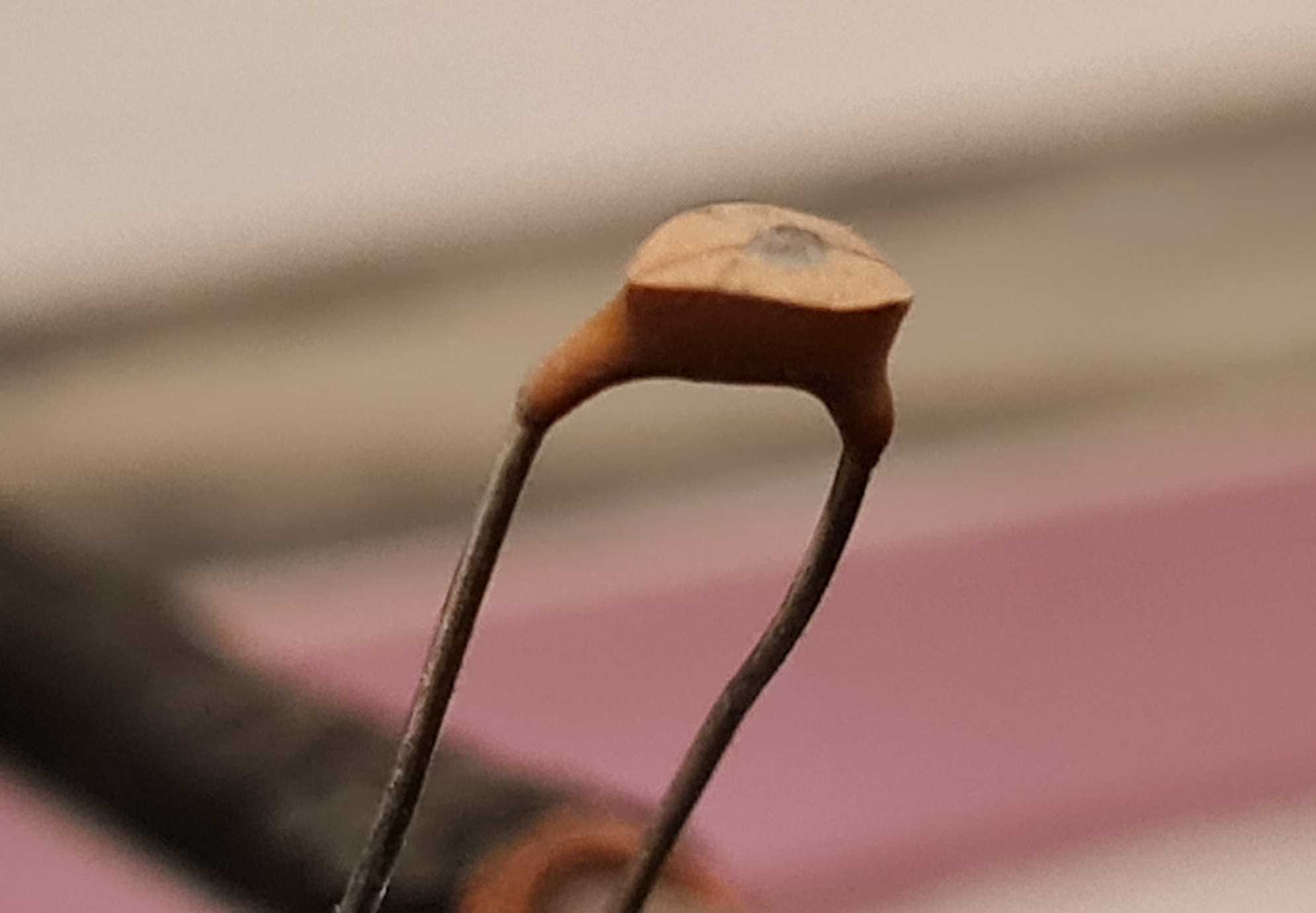
Watching this on the spectrum analyser I filed the capacitor until I got this in the display (tuned circuit in series with a 5K resistor):

The frequency is a little bit low, so tht I can prune it (with the nail-file) when I set up the final filter.
This gives me exactly the capacitance I want with a single capacitor. For 17pf select a 22pf and stat filing. A 10pf can be pulled down to 3.647 without destroying the cap. This particular experiment took the tuned circuit from 160MHz to 265MHz without any problems.
The tuned circuit measurement also works with a GDO and oscilloscope, but maybe not as accurate, unless you use a frequency counter with the GDO. Just sweep, find the dip, and then start filing.
A dab of nail varnish on the cap seals it and does not change the capacitance.
I will add this to the article because it can be done without an analyser and you can get exactly the right capacitances needed for any filter.
BR Harry - SM0VPO
sm0vpo- Admin
- Posts : 110
Join date : 2013-03-26
Age : 72
Location : Märsta, Sweden
Ruud likes this post
Re: FM Transmitter V8
![]() by sm0vpo Tue Aug 16, 2022 11:55 am
by sm0vpo Tue Aug 16, 2022 11:55 am
Thank you very much for the feedback. Each project has something "special" and this project was to show the benefits of a decent output filter.
When I made the PCB I used pads to support two capacitors foe each of the caps. I used 6 holes so that you can select 2.5mm or 5mm lead spacing caps.
3.647pf can be made up using 2.7pf and 1.0pf in parallel (within 1.3%), and the results were more than just good enough.
I built the filter as a standalone filter and used my new analyser (with tracking generator) and found that it could be duplicated with minor deviations from the calculated values, and still perform as it was designed.
I gave realty detailed info for the coils so that it could be duplicated by anyone with a little assembly skill.
As regards the modulation, yes you are 100% correct. I did not check it with the stereo encoder, but my 222 encoder does not give perfect stereo: it gives "reasonable" stereo separation. I could have spent a bit more effort on the modulation but the RC period was reckoned to be about 2µs. I did quickly sweep the modulation input audio response and it seemed rather flat up to about 80kHz or so, but I didn't record any figures. In this case the modulation was not a high priority, but as you pointed out it could be easily improved.
One thing I did notice was then when I connected audio input to it, the frequency jumped and then quickly drifted back onto the correct frequency. This is probably the effect of the 1µf capacitor charging.
Maybe I can update the project sometime, although this was a ""spin-off" from another project, it is simple, stable and a surprisingly good performer. I have the "rats-nest" version at home now connected to my computer (mono) so I can listen to www.bigl.co.uk in the rest of the house and on the terrace/back-garden (with a 20dB attenuator on the output).
Thank you for the comments. It was really interesting to read and I shall think about this in light of your experience. Thank you very much.
Very best regards from Harry - sm0vpo
sm0vpo- Admin
- Posts : 110
Join date : 2013-03-26
Age : 72
Location : Märsta, Sweden
Ruud likes this post
FM Transmitter V8
![]() by Ruud Sat Aug 13, 2022 5:26 pm
by Ruud Sat Aug 13, 2022 5:26 pm
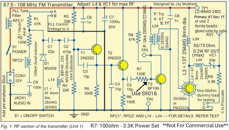
I looked at your V8 transmitter design.
The addition of the output filter is a good thing.
(Although I wonder how to create a 3.647 pF capacitor, or to calibrate the filter without a spectrum analyzer...
But that is not the reason I am reacting.
I notice that there is a 47 K.ohm resistor between the audio input and the varicap/zener diode.
This will work fine for mono.
I have done a lot* of experiments with stereo coders and the coupling of the audio to the varicap in an oscillator.
For the best stereo separation, you need a 'flat' frequency response AND a flat phase respone up to 53 KHz. (Preferably even higher.)
I discovered that higher resistor values between the audio input and the varicap, degraded the channel separation.
Probably because of the low-pass filter effect (series R, parallel tuning capacitor, capacity of the varicap etc.)
I assume that for most people 'just stereo' is good enough, but if you are going to take channel separartion measurements, the difference with a lower value coupling resistor will be obvious.
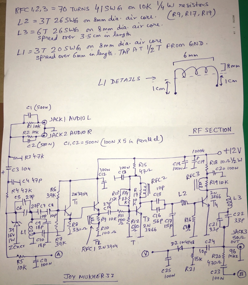
I discovered that a small inductance (instead of a resistor) gave much better results when it comes to channel separation.
* I did these experiments, because (long time ago!) I was asked to build a transmitter for a 'commercial' pirate station at the time.
They wanted the best audio quality and the best stereo.
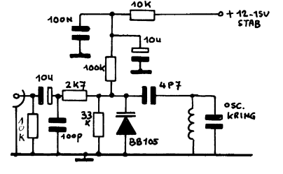
Here is an example of a different design; the input is decoupled for HF and the resistor value between the input and the varicap is very low: 2.7 K.ohm.
Of course a lower resistor value will have an effect on the 'Q' of the tuned circuit.
Ruud- Posts : 130
Join date : 2012-11-26
Age : 68
Location : Haule, The Netherlands -
sm0vpo likes this post