144-148MHz PLL with discrete chips.


144-148MHz PLL with discrete chips.
![]() by dare4444 Sat Sep 17, 2022 8:20 am
by dare4444 Sat Sep 17, 2022 8:20 am
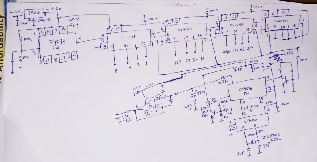
This PLL control unit as shown covers the 2m ham band in 5KHz steps. The twelve inputs to 74HC193 could be driven directly by digital pins of an Arduino Nano. A LCD and rotary encoder should be added.
The circuit should work from 15KHz to 160MHz in 5KHz steps if the BCD input to fourth 74HC193 is made flexible. Currently the number four 74HC193 is hard-wired to divide by 28,672 to enable the circuit to work on the 2m band. To cover 144-148MHz the total divider number should be between 28,800 - 29,600. The loop filter at the output of CD4046 is wide enough and allows WBFM if the circuit is used with a 87.5-108MHz FM oscillator.
The use of a /4 prescaler built around 74F74 high speed flip-flop keeps it simple and allows 1.25KHz reference frequency for the PLL. No dual-modulus prescaler needed!
An Arduino should easily drive all four 74HC193 chips. Analog input pins are also usable as digital output pins. A0 will be D14, A11 will be D15, and so on. There are enough pins to add a serial LCD display and rotary encoder for easy control of this synthesizer.
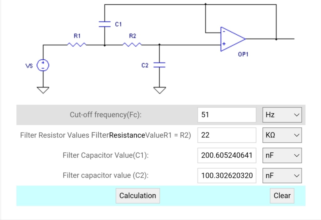
Image 1: TL071 active low pass filter values. It removes the audible 1.25KHz reference tone.
Image 2: PLL synthesizer. The RFC should be a 1mH inductor.
The circuit should work from 15KHz to 160MHz in 5KHz steps if the BCD input to fourth 74HC193 is made flexible. Currently the number four 74HC193 is hard-wired to divide by 28,672 to enable the circuit to work on the 2m band. To cover 144-148MHz the total divider number should be between 28,800 - 29,600. The loop filter at the output of CD4046 is wide enough and allows WBFM if the circuit is used with a 87.5-108MHz FM oscillator.
The use of a /4 prescaler built around 74F74 high speed flip-flop keeps it simple and allows 1.25KHz reference frequency for the PLL. No dual-modulus prescaler needed!
An Arduino should easily drive all four 74HC193 chips. Analog input pins are also usable as digital output pins. A0 will be D14, A11 will be D15, and so on. There are enough pins to add a serial LCD display and rotary encoder for easy control of this synthesizer.
Image 1: TL071 active low pass filter values. It removes the audible 1.25KHz reference tone.
Image 2: PLL synthesizer. The RFC should be a 1mH inductor.

dare4444- Posts : 427
Join date : 2013-03-19
» PLL with discrete chips - Upgrade Joy design solving major issue - V2.0
» Discrete PLL for single transistor FM transmitter
» new HTML page : "No to Zeners & Regulator Chips" -> lot of PNP NPN symbol errors in schematics
» Discrete PLL for single transistor FM transmitter
» new HTML page : "No to Zeners & Regulator Chips" -> lot of PNP NPN symbol errors in schematics
Permissions in this forum:
You can reply to topics in this forum