RF generator circuit for designing/testing circuits for HAM radio
4 posters


Re: RF generator circuit for designing/testing circuits for HAM radio
![]() by Ivan Sat May 06, 2023 5:10 pm
by Ivan Sat May 06, 2023 5:10 pm
Hi,
I expect the oscillator pair should be always connected to the emitter of the current source. The regulating transistor must therefore be PNP if the oscillator is NPN. A regulator loaded in the collector has different properties.
Why is a diode between the collectors of oscillating transistors?
VBR from Ivan
Ivan- Posts : 793
Join date : 2012-11-25
Age : 64
Location : Praha, Czechia
Re: RF generator circuit for designing/testing circuits for HAM radio
![]() by MrWifiHifi Sat May 06, 2023 1:39 pm
by MrWifiHifi Sat May 06, 2023 1:39 pm
As far as I know, there are two ways to build an oscillator. Either with the use of NPN or PNP transistors, but I have also seen a circuit with JFET transistors somewhere.
As for tuning, I don't know what would be better. Whether to use a rotary tuning capacitor and varicap for detuning or just purely varicap.
For that diode range switching, I wanted to use it to avoid mechanical switches.
I would also be interested in the stability of the output amplitude during detuning and also whether the given oscillator can oscillate at higher (144MHz) and lower (100KHz) frequencies.
It is about the fact that I would like to build a device for working with RF circuits using parts that have been discarded (they are still functional, but the devices in which they were used are no longer used)
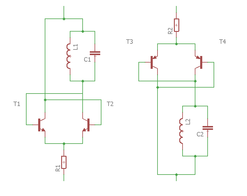
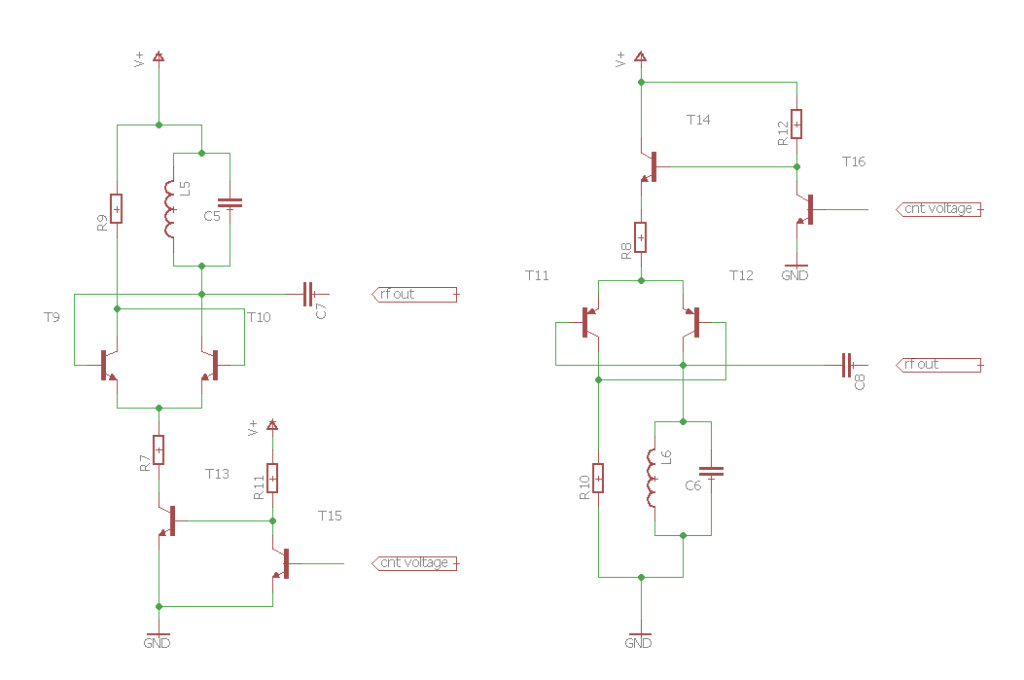
In the attachment I am attaching the wiring with PNP and NPN transistors, I would be happy for feedback whether it can or cannot be this way.
I would also like to add that the connections that I have yet found did not have the base-emitter terminals directly connected, a capacitor and a resistor were still connected. Does anyone know what makes it better than being connected directly?

As for tuning, I don't know what would be better. Whether to use a rotary tuning capacitor and varicap for detuning or just purely varicap.
For that diode range switching, I wanted to use it to avoid mechanical switches.
I would also be interested in the stability of the output amplitude during detuning and also whether the given oscillator can oscillate at higher (144MHz) and lower (100KHz) frequencies.
It is about the fact that I would like to build a device for working with RF circuits using parts that have been discarded (they are still functional, but the devices in which they were used are no longer used)
In the attachment I am attaching the wiring with PNP and NPN transistors, I would be happy for feedback whether it can or cannot be this way.
I would also like to add that the connections that I have yet found did not have the base-emitter terminals directly connected, a capacitor and a resistor were still connected. Does anyone know what makes it better than being connected directly?
MrWifiHifi- Posts : 21
Join date : 2022-06-21
RF generator circuits
![]() by John_1981 Tue May 02, 2023 10:20 pm
by John_1981 Tue May 02, 2023 10:20 pm
The circuit with the cross coupled pair of PNP transistors worked well for me (the first image with the amplitude stabilised output), i tried it out when looking for a wide range VCO as part of a synthesizer. Unlike colpitts, hartley, etc. it would oscillate reliably with any old coil from a mains transformer primary winding to a VHF choke. I used 2x BC557 PNP devices. I used a red LED as a shunt regulator to power the circuit as anything over about 1.5-2.0V causes the waveform to be distorted. From what I can recall I achieved a tuning range of at least 4:1 with varicap tuning. Have a look for "BH1RBG RF lab", theres some interesting oscillator circuits on there.
Regards,
JC
Regards,
JC
John_1981- Posts : 32
Join date : 2021-11-07
Re: RF generator circuit for designing/testing circuits for HAM radio
![]() by Ivan Tue May 02, 2023 4:10 pm
by Ivan Tue May 02, 2023 4:10 pm
Hi,MrWifiHifi wrote: I would change such as tuning with a varicap
reaching the tuning range more than 1:6 with good stability may be a tough task with varicaps. A quality air variable capacitor (on ceramics, with ball bearings) with a suitable gear is hard to find, but may be better.
Why not, but what is the benefit?switching the LC circuits (ranges) with diodes (some designs used a rotary switch to select the ranges)
It would require a negative power supply and a PNP regulator (T6) if you want to keep the type of oscillator.changing the PNP to NPN transistors in the oscillator.
That IC is also quite obsolete. It contains NPN transistors, so see the previous statement.I also wondered if the MA3006 (CA3006) circuit could be used for the oscillator part, transistors T1 and T2 would be used for the oscillator and T3 would be used as an amplitude regulator. But that's just an idea.
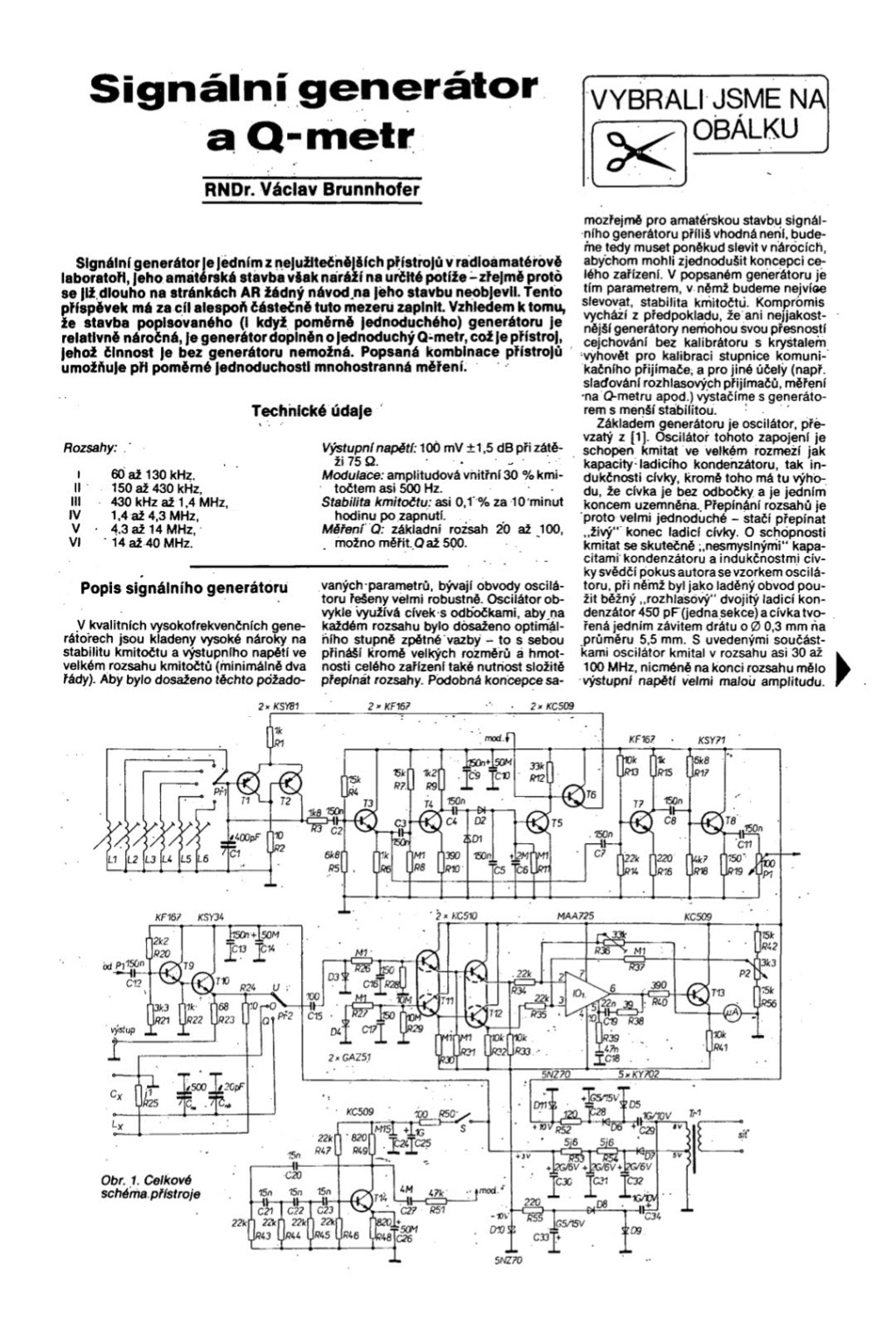
AM can be injected into the base of T5 if the 2u capacitor is removed. FM would require a varicap in parralel with L, which is not a problem.Furthermore, I would like to add the option of AM and FM modulation (for FM tuning with a power varicap), 1KHz and 400Hz generators,
The length of leads is not so big problem on HF, if you keep them short. On the other hand, SMD is more "eye-candy" and most components have direct SMD replacements. The germanium diodes could be replaced with Schottky SMD ones.Finally, I would just like to ask if it might not be better to build something like this with SMD components, since they are better for RF.
VBR from Ivan
Ivan- Posts : 793
Join date : 2012-11-25
Age : 64
Location : Praha, Czechia
Re: RF generator circuit for designing/testing circuits for HAM radio
![]() by MrWifiHifi Tue May 02, 2023 11:43 am
by MrWifiHifi Tue May 02, 2023 11:43 am
I am glad that it can still be built and used today. There are a few things I would change such as tuning with a varicap, switching the LC circuits (ranges) with diodes (some designs used a rotary switch to select the ranges) and probably changing the PNP to NPN transistors in the oscillator.
I also wondered if the MA3006 (CA3006) circuit could be used for the oscillator part, transistors T1 and T2 would be used for the oscillator and T3 would be used as an amplitude regulator. But that's just an idea.
Furthermore, I would like to add the option of AM and FM modulation (for FM tuning with a power varicap), 1KHz and 400Hz generators, and finally a unit for coarse and fine tuning with op amps.
Finally, I would just like to ask if it might not be better to build something like this with SMD components, since they are better for RF.
MrWifiHifi- Posts : 21
Join date : 2022-06-21
Re: RF generator circuit for designing/testing circuits for HAM radio
![]() by Ivan Tue May 02, 2023 10:50 am
by Ivan Tue May 02, 2023 10:50 am
Hi Ruud,
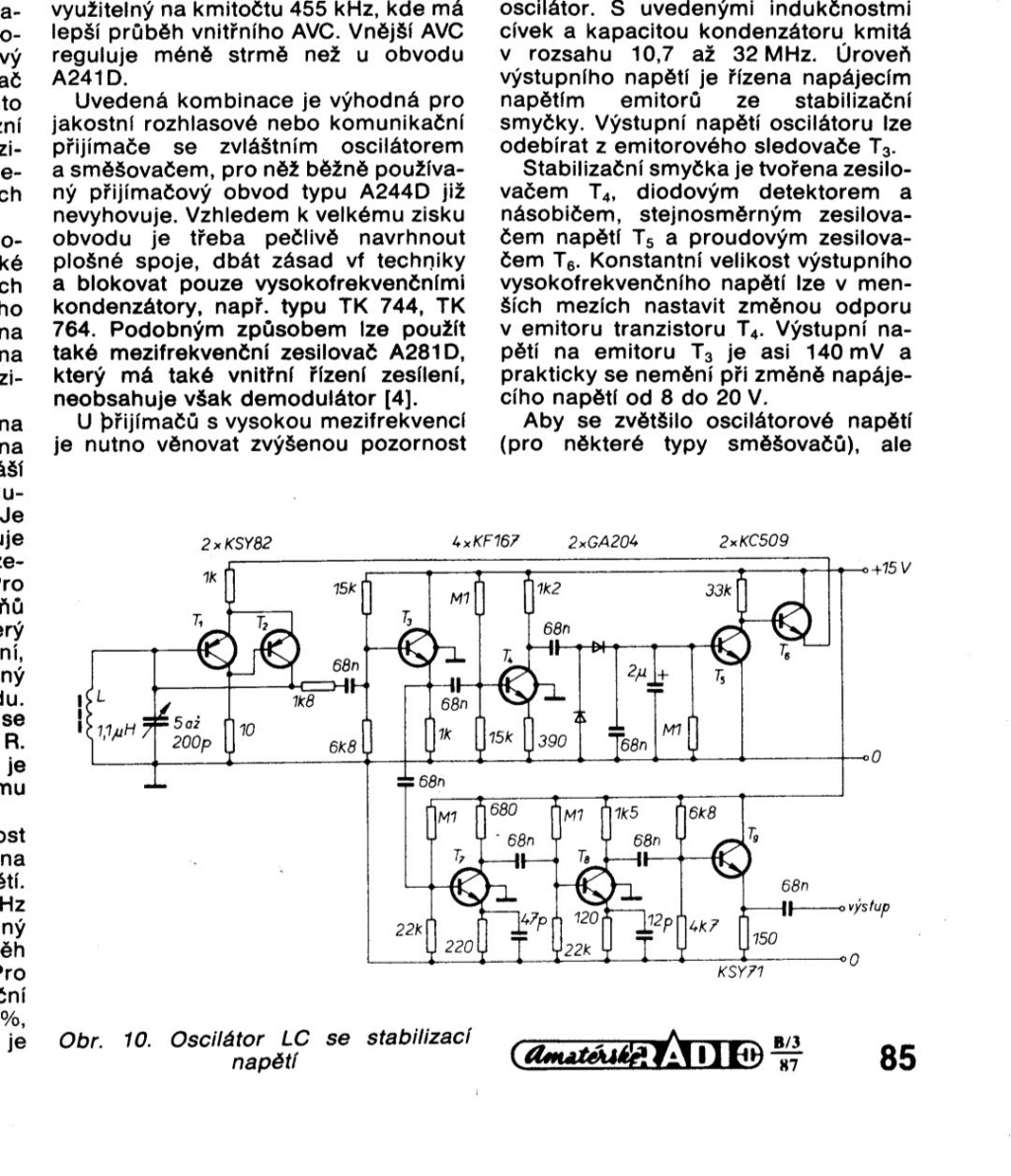
the generator is intended to be a general purpose device covering several HF ham bands without switching. IMHO it is reasonable to keep +- stable output level while tuning the oscillator.
The output voltage of a mere emitter follower would be too small for some puroses. It is better to amplify the signal more and add a switchable output attenuator (not drawn).
VBR from Ivan OK1SIP
Ivan- Posts : 793
Join date : 2012-11-25
Age : 64
Location : Praha, Czechia
Re: RF generator circuit for designing/testing circuits for HAM radio
![]() by Ruud Tue May 02, 2023 9:25 am
by Ruud Tue May 02, 2023 9:25 am
Looking at schematic 'screen 10', one can ask the question how important the amplitude stabilisation is for average use.
And is it really necessary to have three transistors as amplifier/buffer after the oscillator?
If you don't need the higher level, I suppose a simple emitter follower would be sufficient after the oscillator (T1/T2).
And is it really necessary to have three transistors as amplifier/buffer after the oscillator?
If you don't need the higher level, I suppose a simple emitter follower would be sufficient after the oscillator (T1/T2).
Last edited by Ruud on Tue May 02, 2023 11:14 am; edited 1 time in total

Ruud- Posts : 130
Join date : 2012-11-26
Age : 68
Location : Haule, The Netherlands -

Re: RF generator circuit for designing/testing circuits for HAM radio
![]() by Ivan Tue May 02, 2023 7:39 am
by Ivan Tue May 02, 2023 7:39 am
Hi,
these schematics are very promising even nowadays, although no. 2 and 3 seem to be rather complicated for beginners. They all employ old czechoslovak Tesla parts, so some re-evaluation with western ones would be necessary for most hams of the world. Thank you anyway!
VBR from Ivan OK1SIP
these schematics are very promising even nowadays, although no. 2 and 3 seem to be rather complicated for beginners. They all employ old czechoslovak Tesla parts, so some re-evaluation with western ones would be necessary for most hams of the world. Thank you anyway!
VBR from Ivan OK1SIP
Ivan- Posts : 793
Join date : 2012-11-25
Age : 64
Location : Praha, Czechia
RF generator circuit for designing/testing circuits for HAM radio
![]() by MrWifiHifi Tue May 02, 2023 1:36 am
by MrWifiHifi Tue May 02, 2023 1:36 am
Hello
I came across these RF generator connections in old timers. I would like to ask if anyone has built something similar, or what are the parameters of such generators and if they are worth building. I'm interested mainly because a lot of HAM radio beginners don't have access to professional equipment, but they do have access to old parts, and maybe they would be able to build something like that. Alternatively, if this would not be suitable, what RF generator would you advise to build? Something simple and to meet the parameters for testing and setting up RF circuits as much as possible.
I came across these RF generator connections in old timers. I would like to ask if anyone has built something similar, or what are the parameters of such generators and if they are worth building. I'm interested mainly because a lot of HAM radio beginners don't have access to professional equipment, but they do have access to old parts, and maybe they would be able to build something like that. Alternatively, if this would not be suitable, what RF generator would you advise to build? Something simple and to meet the parameters for testing and setting up RF circuits as much as possible.
MrWifiHifi- Posts : 21
Join date : 2022-06-21
Sponsored content
» old radio circuits
» Simple radio circuit (AM)
» Designing transformers
» Tuned Circuits Article - re: Impedance
» Testing tetrode tube
» Simple radio circuit (AM)
» Designing transformers
» Tuned Circuits Article - re: Impedance
» Testing tetrode tube
Permissions in this forum:
You can reply to topics in this forum