V7 FM Transmitter questions
3 posters


Re: V7 FM Transmitter questions
![]() by admin Sun Dec 23, 2012 1:35 pm
by admin Sun Dec 23, 2012 1:35 pm
dk-info wrote:Thank you for the reply, I will indeed use a FET (BS170 for example) to switch transmitter power during pauses.
As for the sine wave input to the transmitter, I will integrate a square wave off the controller pin using a pair of single ended LM324's.
This "sine wave" will have a DC bias; what should the peak to peak voltage be to the AF input ("Sine Out" in the circuit below) with
respect to ground? Would you use a different integrator scheme? I am looking at a 1kHz tone, what would you suggest the
integrator RC values be?
Interesting. I recently wrote a program for the PIC12F509 that was a beacon identification signal for SK5CT (Uppsala Radioklubben). The program simply sent a loooong CW ident, location and info signal repeatedly, but it would be a really simple case to change it for a repeater periodic ident, or whatever you want.
The chip gave out PPT keying, CW keying and also CW-tone out /square wave). A simple band-pass filter is all that is needed to make it a sine, but most FM radios these days have a decent audio stage so stuffing a (nearly) square wave into the mic should not do anything wrong. The 300Hz - 3.4kHz AF stage should already be the filtering needed.
If you are interested I can share the code with you.
Very best regards from Harry - SM0VPO
_________________
Everything in this world is either bacon, or it isn't bacon
They say that money cannot bring you happiness, but if you have it then you can always buy more bacon

admin- Admin
- Posts : 1144
Join date : 2012-11-24
Age : 72
Location : Märsta, Sweden -

Re: V7 FM Transmitter questions
![]() by Ivan Thu Dec 20, 2012 8:23 am
by Ivan Thu Dec 20, 2012 8:23 am
Hi David,
IMHO a simple passive network consisting of two resistors in the signal path and two grounded capacitors would do. A third capacitor between this network and the V7 AF input is desirable, otherwise the DC component of the audio will shift the TX frequency.
If you insisted on using opamp integrators, you should tie their noniverting inputs to a 2,5 V bias. A voltage divider on the output may be necessary, as the V7 TX requires cca 0,2 V RMS on its AF input.
BR from Ivan
Ivan- Posts : 793
Join date : 2012-11-25
Age : 64
Location : Praha, Czechia
FM Radio Beacon
![]() by dk-info Wed Dec 19, 2012 5:11 pm
by dk-info Wed Dec 19, 2012 5:11 pm
Thank you for the reply, I will indeed use a FET (BS170 for example) to switch transmitter power during pauses.
As for the sine wave input to the transmitter, I will integrate a square wave off the controller pin using a pair of single ended LM324's.
This "sine wave" will have a DC bias; what should the peak to peak voltage be to the AF input ("Sine Out" in the circuit below) with
respect to ground? Would you use a different integrator scheme? I am looking at a 1kHz tone, what would you suggest the
integrator RC values be?
Circuit Example: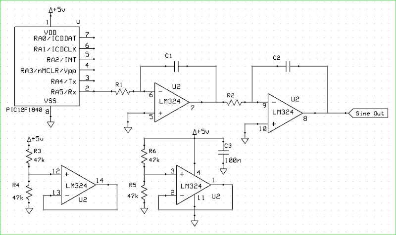
It is painfully obvious I am not an analogue guy, any help is greatly appreciated.
David Wurmfeld
Melbourne, Florida
dk-info- Posts : 2
Join date : 2012-12-18
Age : 67
Location : Melbourne, Florida
Re: V7 FM Transmitter questions
![]() by Ivan Wed Dec 19, 2012 11:12 am
by Ivan Wed Dec 19, 2012 11:12 am
Hi David,
a sinewave is better as the modulating signal. A dual integrating RC network should be sufficient.
It might be a good idea to use another MCU pin to switch the transmitter off in the pauses.
BR from Ivan
a sinewave is better as the modulating signal. A dual integrating RC network should be sufficient.
It might be a good idea to use another MCU pin to switch the transmitter off in the pauses.
BR from Ivan
Ivan- Posts : 793
Join date : 2012-11-25
Age : 64
Location : Praha, Czechia
V7 FM Transmitter questions
![]() by dk-info Tue Dec 18, 2012 5:42 pm
by dk-info Tue Dec 18, 2012 5:42 pm
Is this circuit available as a kit? I would be very interested in purchasing one.
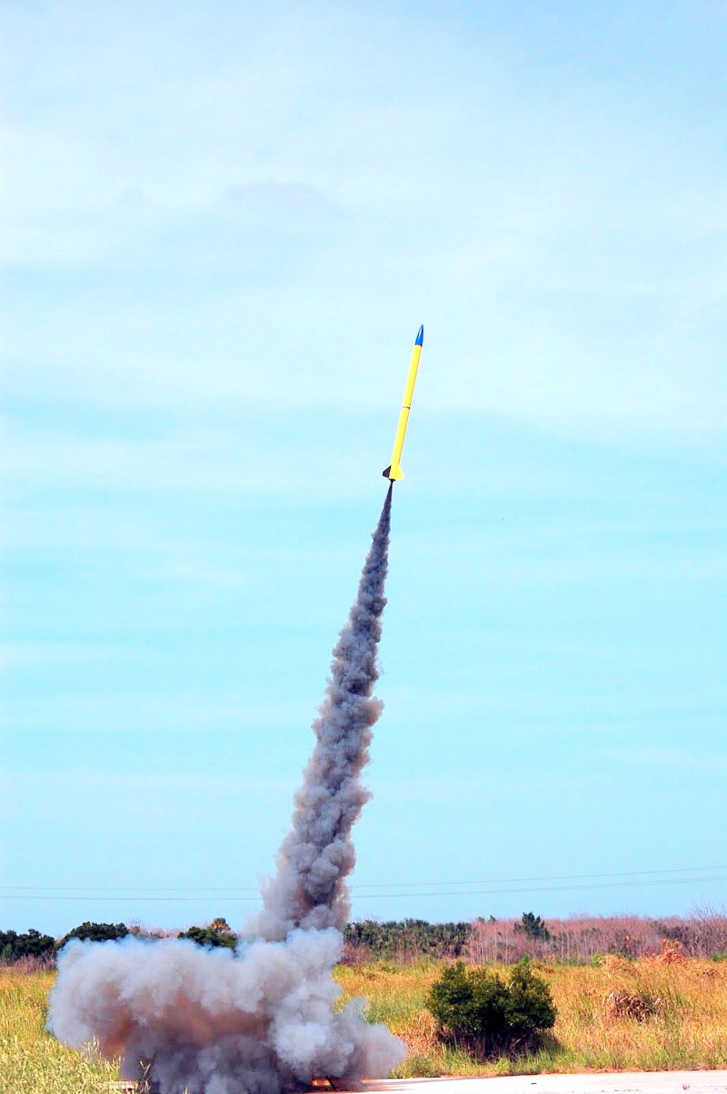
I would like to use the transmitter as a beacon to locate my high power rocket when it is lost in the trees or bushes.
What are the normal input characteristics for the AF input signal?
Forgive my ignorance, I would like to drive the transmitter from the output pin of a microcontroller, from a square wave of about 1kHz.
I would pulse the transmitter at this frequency for a half second every three seconds, then every ten minutes transmit my call sign in Morse code.
Would a simple resistor divider on the AF input be sufficient?
Thank you in advance for your kind attention to my question,
David Wurmfeld,
Melbourne Florida
dk-info- Posts : 2
Join date : 2012-12-18
Age : 67
Location : Melbourne, Florida
Permissions in this forum:
You can reply to topics in this forum