All valve receiver modification
3 posters


Re: All valve receiver modification
![]() by admin Thu Jun 11, 2020 7:46 pm
by admin Thu Jun 11, 2020 7:46 pm
Hi Ivan and Vulkan,
I use 230V AC transformers as speaker transformers, connected backwards.
I have found that if you dismantle the transformer, then re-assemble with ALL the "E"-formers from one side and all the "I"-formers at the other side, a bit of 0.1mm paper can be put between them, making the transformer suitable to have a DC bias current through it without saturation.
I think I described this on one valve project on the homepages.
BR Harry
_________________
Everything in this world is either bacon, or it isn't bacon
They say that money cannot bring you happiness, but if you have it then you can always buy more bacon

admin- Admin
- Posts : 1144
Join date : 2012-11-24
Age : 72
Location : Märsta, Sweden -

Re: All valve receiver modification
![]() by Ivan Thu Jun 11, 2020 10:32 am
by Ivan Thu Jun 11, 2020 10:32 am
Yes, this power transformer is good. It lacks a heater winding for the rectifier tube, but you probably intend using a diode bridge instead.
AF output transformers are often matched to a specific pentode type and schematic. It may be the best way to salvage a complete AF PA circuitry from an old tube radio (TV, tape recorder etc.) and connect it to the volume potentiometer.
Notice the tapping of the primary (anode) winding in the original schematic. This is not everywhere. And do not forget the proper air gap in the core, needed to prevent core saturation by the DC component of anode current.
BR from Ivan
Ivan- Posts : 793
Join date : 2012-11-25
Age : 64
Location : Praha, Czechia
Re: All valve receiver modification
![]() by vulkan Thu Jun 11, 2020 9:06 am
by vulkan Thu Jun 11, 2020 9:06 am
This transformer also has a 6.3v - 5A output.
I prefer that the transformer be oversized, in case it can also be used in the transmitter.
As for the AF transformer, I have not looked for it yet. Should it be 4000 ohm - 8 ohm 5w?

I prefer that the transformer be oversized, in case it can also be used in the transmitter.
As for the AF transformer, I have not looked for it yet. Should it be 4000 ohm - 8 ohm 5w?
vulkan- Posts : 16
Join date : 2020-06-07
Re: All valve receiver modification
![]() by Ivan Wed Jun 10, 2020 8:33 pm
by Ivan Wed Jun 10, 2020 8:33 pm
Hi,
I expect you had the PSU transformer in mind. 170 VAC should yield 240 VDC with a two way rectifier. 130 mA looks rather like an overkill, but you can use it of course. What about heater winding(s)?
The AF output transformer primary may present a problem. Do you have some data about it?
BR from Ivan
Ivan- Posts : 793
Join date : 2012-11-25
Age : 64
Location : Praha, Czechia
Re: All valve receiver modification
![]() by vulkan Wed Jun 10, 2020 12:52 pm
by vulkan Wed Jun 10, 2020 12:52 pm
Good Morning.
I have located a 170v-130mA AC output transformer
Is that transformer suitable?
I have located a 170v-130mA AC output transformer
Is that transformer suitable?
vulkan- Posts : 16
Join date : 2020-06-07
Re: All valve receiver modification
![]() by vulkan Mon Jun 08, 2020 8:27 pm
by vulkan Mon Jun 08, 2020 8:27 pm
Thanks for answering.
Like the F.I. it is 5mhz, the BFO I think should be 5,0015mhz and the capacitors 330pf
Must try.
Thank you
Like the F.I. it is 5mhz, the BFO I think should be 5,0015mhz and the capacitors 330pf
Must try.
Thank you
vulkan- Posts : 16
Join date : 2020-06-07
Re: All valve receiver modification
![]() by Ivan Mon Jun 08, 2020 7:56 pm
by Ivan Mon Jun 08, 2020 7:56 pm
Hi Vulkan,
replace the variable capacitor and coil in the grid circuit of V2b by a suitable crystal with parralel grid leak resistor. Adjust values of the capacitor divider if necessary.
As for the frequency of the crystal, please look here.
BR from Ivan
replace the variable capacitor and coil in the grid circuit of V2b by a suitable crystal with parralel grid leak resistor. Adjust values of the capacitor divider if necessary.
As for the frequency of the crystal, please look here.
BR from Ivan
Ivan- Posts : 793
Join date : 2012-11-25
Age : 64
Location : Praha, Czechia
Re: All valve receiver modification
![]() by vulkan Mon Jun 08, 2020 6:20 pm
by vulkan Mon Jun 08, 2020 6:20 pm
Good afternoon.
My name is: Manolo
I have seen all valve receiver and would like to modify it to receive only 7mhz LSB.
I am sending you the modification of the F.I. and I would like you to indicate the modification to put an XTAL in BFO.
Thank you
My name is: Manolo
I have seen all valve receiver and would like to modify it to receive only 7mhz LSB.
I am sending you the modification of the F.I. and I would like you to indicate the modification to put an XTAL in BFO.
Thank you
vulkan- Posts : 16
Join date : 2020-06-07
All valve receiver modification
![]() by vulkan Mon Jun 08, 2020 6:18 pm
by vulkan Mon Jun 08, 2020 6:18 pm
Buenas tardes.
Mi nombre es manolo
He visto todos los receptores de válvula y me gustaría modificarlo para recibir solo 7 mhz LSB.
Le estoy enviando la modificación de la FI y me gustaría que indique la modificación para poner un XTAL en BFO.
Gracias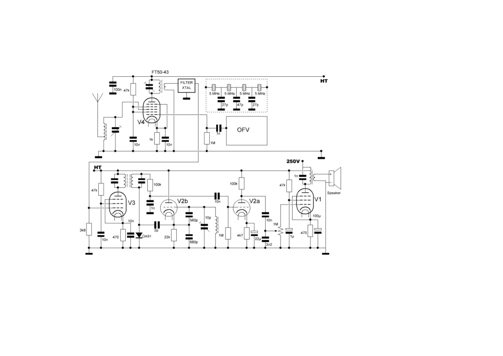
Mi nombre es manolo
He visto todos los receptores de válvula y me gustaría modificarlo para recibir solo 7 mhz LSB.
Le estoy enviando la modificación de la FI y me gustaría que indique la modificación para poner un XTAL en BFO.
Gracias
vulkan- Posts : 16
Join date : 2020-06-07
» ALL VALVE RECEIVER poor sensitivity
» ALL VALVE RECEIVER inductor former sizes
» Vectronics 1290K AM TX modification with 4 transistors
» Harry's Two-valve CW TX
» 2 valve transmitter
» ALL VALVE RECEIVER inductor former sizes
» Vectronics 1290K AM TX modification with 4 transistors
» Harry's Two-valve CW TX
» 2 valve transmitter
Permissions in this forum:
You can reply to topics in this forum|
|
|