GRID DIP OSCILLATOR by Harry Lythall - SM0VPO question


Page 2 of 2 •  1, 2
1, 2
GRID DIP OSCILLATOR by Harry Lythall - SM0VPO question
![]() by zsolt1 Mon Dec 18, 2017 7:54 pm
by zsolt1 Mon Dec 18, 2017 7:54 pm
hi, i recently built the GRID DIP OSCILLATOR by Harry Lythall - SM0VPO . It works like charm . I would like to use a frequency meter attached to it . I have several frequency meters built with PIC16F microcontrollers, some have some kind of input signal conditioning and some not . My trouble is that when i directly connect the frequency meter in whatever point, it kills the oscillator or it considerably changes it's frequency . The only way i could measure frequency is with one pick up coil of 1 or 2 turns placed near the GDO .
I would like to use a input pin (ex. timer0 clock input) with TTL level to get the frequency , what circuit should i search for ?
Thanks
zsolt1- Guest
Re: GRID DIP OSCILLATOR by Harry Lythall - SM0VPO question
![]() by zsolt Thu Feb 08, 2018 11:37 pm
by zsolt Thu Feb 08, 2018 11:37 pm
I'm trying to tweak around the dc-dc source . My newest idea is that there is no need for the buck-boost pair . I believe that only the boost will do the job . If i use a 1/4 voltage divider to feed the varicap's than the boost converter should range from 9 to 48 V before the voltage divider .

I would also change the mosfet for a bjt tranzistor . What tranzistor would you suggest ? The operating frequency is <60kHz ( Uce <60v , Ic <100mA i belive )
zsolt- Posts : 209
Join date : 2017-12-19
Re: GRID DIP OSCILLATOR by Harry Lythall - SM0VPO question
![]() by zsolt Mon Feb 05, 2018 7:42 pm
by zsolt Mon Feb 05, 2018 7:42 pm
i'm trying to get some documentation about how this is done in TV's (no need to reinvent the wheel
I will take some time until i put something in practice from all this ... now in my ''free'' time i'm mounting polystyrene plates , mounting doors ... house stuff .
By the way have you thought about using also varicap's just without a uC in your versions ?
I don't know about how linear this could be , but i think it's easier to draw a dial around a potentiometer than a variable condensator ? Or there could be some other benefits / drawbacks ... ? Oh or maybe a linear potentiometer can be used , those long ones like in dj mixers .
Now is somewhat hard to get new varicaps , i intend to use 24V zeners i have already .
The dc blocking capacitor and the zenner capacitance equivalent calculates like the case of normal series capacitor connection ?
zsolt- Posts : 209
Join date : 2017-12-19
Re: GRID DIP OSCILLATOR by Harry Lythall - SM0VPO question
![]() by John_1981 Sun Feb 04, 2018 11:07 pm
by John_1981 Sun Feb 04, 2018 11:07 pm
John_1981- Guest
oscilloscope
![]() by John_1981 Sun Feb 04, 2018 11:06 pm
by John_1981 Sun Feb 04, 2018 11:06 pm
John_1981- Guest
Re: GRID DIP OSCILLATOR by Harry Lythall - SM0VPO question
![]() by admin Sun Feb 04, 2018 4:22 pm
by admin Sun Feb 04, 2018 4:22 pm
I think it is looking good. l will be really interested to hear how it works in practice. The tuning range will be a bit different, but your should go to much higher frequencies than mine due to the reduce tuning capacitance.
If you need more, then don't forget that you can put varicaps (or Zeners) in parallel.
BR Harry - SM0VPO
admin- Admin
- Posts : 1144
Join date : 2012-11-24 -

Re: GRID DIP OSCILLATOR by Harry Lythall - SM0VPO question
![]() by zsolt Sun Feb 04, 2018 2:47 pm
by zsolt Sun Feb 04, 2018 2:47 pm
for now i can only do theory ... i will make time for this later .
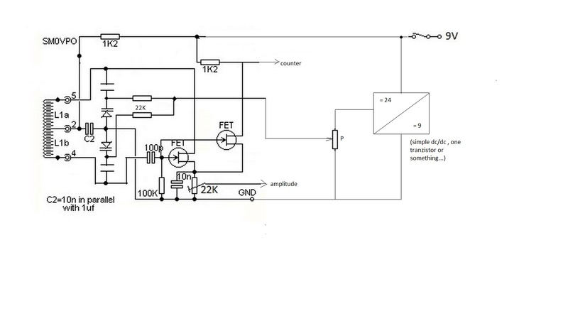
I added the dc dc convertor i mentioned . I'm not shore if it works like this , the buck part works for shore, i built an MPPT solar charger with it (and the small Arduino board) .

An other option would be to build a separate (analog) boost to feed the buck converter .
When voltage below 9 V is needed , PWM1 is in zero state so the circuit is in Buck mode . When voltage above 9 V is needed PWM2 is in 1 state so the circuit is working in boost mode . At least this is how i imagined things so far . Also i used to do some rudimental digital filtering (running average
I think , i will give it a try with the Arduino uno board . ( the pwm duty cycle control register is only 8 bit , this will be a challenge
zsolt- Posts : 209
Join date : 2017-12-19
Re: GRID DIP OSCILLATOR by Harry Lythall - SM0VPO question
![]() by admin Sun Feb 04, 2018 10:18 am
by admin Sun Feb 04, 2018 10:18 am
Please do let me know how you get on this this. I am sure that all here are interested in this thread :-)
BR Harry - SM0VPO
admin- Admin
- Posts : 1144
Join date : 2012-11-24 -
Re: GRID DIP OSCILLATOR by Harry Lythall - SM0VPO question
![]() by zsolt Sun Feb 04, 2018 7:40 am
by zsolt Sun Feb 04, 2018 7:40 am
i think i can easily generate the 2 ... 12 V control voltage with the uC itself , by using a suitable dc-dc converter and one of the uC's pwm pin. So i don't need to waste pins of the uC with the ADC module .
I recently built a buck converter with a small Arduino board (i found that pin 6 of that little board can work in pwm mode up to 65kHz ). I also found some simple buck-boost topology in one single circuit
Now i only need to figure out the thing with the varicap diodes. For now i come up with the circuit below :
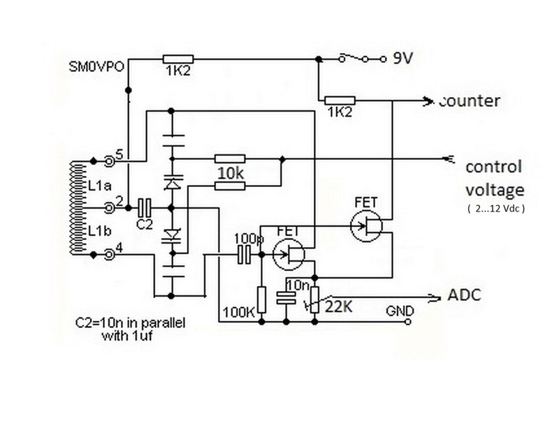
I have found some connections on the net with these diodes . I actually never seen one . So the drawing is how i imagined that it could work (younger papanasos simply can't understand diods as capacitors
I remember when i first built your circuit when trying to connect a frequency meter , all most everything i did it killed the oscillator , and now i'm talking about inserting 12 V in the middle of it .... if this works
zsolt- Posts : 209
Join date : 2017-12-19
Re: GRID DIP OSCILLATOR by Harry Lythall - SM0VPO question
![]() by admin Sat Feb 03, 2018 7:36 pm
by admin Sat Feb 03, 2018 7:36 pm
You are exactly correct.
As a matter of interest, varicap diodes only need a DC voltage that is higher then the peak RF voltage. If you are using a 9v battery for the GDO then a 12v supply would be fine. Also, vaicaps require the highr voltages to get the smaller capacitances. The maximum capacitance occurs at about 2V. You can also use ordinary zener diodes, which have a very high capacitance, compared to real varicap diodes. Just be sure the zener voltage is greater than the max DC you intend to apply.
BR Harry
admin- Admin
- Posts : 1144
Join date : 2012-11-24 -
Re: GRID DIP OSCILLATOR by Harry Lythall - SM0VPO question
![]() by zsolt Wed Jan 31, 2018 9:51 pm
by zsolt Wed Jan 31, 2018 9:51 pm
if i understand well , there is no RF on the source, but there is RF in the drain .
Anyway everything should be clear now, meantime i came up with an other crazy idea , the uC should first find the dipp by itself and then measure the frequency . Since i don't know how to use varicap diodes in your schematic i came up with the idea that the uC can drive a little stepper ganged with the variable condensator .

Of course if i could use varicap diodes would be much better . I would use a 10 bit R-2R DAC to generate control voltage for varicaps . I read that these diodes should get voltages up to 28 V .
My grandmother uses everyday a cup of red vine for blood treatment. Could be something around this treatment , now she is 88
Best regards .
zsolt- Posts : 209
Join date : 2017-12-19
Re: GRID DIP OSCILLATOR by Harry Lythall - SM0VPO question
![]() by admin Wed Jan 31, 2018 11:36 am
by admin Wed Jan 31, 2018 11:36 am
zsolt wrote:Hi,
I modified drawing again to depict what i understood
Is it right ? the trim pot would be the 22K you told to use
Thanks
Hi again, sorry about the delay responding.
Yes, the picture is perfect with the extra FET. As one other pointed out, the source of the transistor has DC on it, so you don't need a diode detector. There should be little or no RF there.
Anyway, hafta shower and dress - off to hospital today to see how my blood is doing. I failed the blood test so they have to drain some blood. Probably why I am aways so tired.
Do you have all the info you need now?
BR Harry
_________________
Everything in this world is either bacon, or it isn't bacon
They say that money cannot bring you happiness, but if you have it then you can always buy more bacon

admin- Admin
- Posts : 1144
Join date : 2012-11-24
Age : 72
Location : Märsta, Sweden -
Re: GRID DIP OSCILLATOR by Harry Lythall - SM0VPO question
![]() by zsolt Mon Jan 15, 2018 4:09 pm
by zsolt Mon Jan 15, 2018 4:09 pm
I modified drawing again to depict what i understood
Is it right ? the trim pot would be the 22K you told to use
Thanks
zsolt- Posts : 209
Join date : 2017-12-19
Re: GRID DIP OSCILLATOR by Harry Lythall - SM0VPO question
![]() by Densil Sun Jan 14, 2018 11:23 pm
by Densil Sun Jan 14, 2018 11:23 pm
/D
Densil- Posts : 47
Join date : 2017-01-06
Re: GRID DIP OSCILLATOR by Harry Lythall - SM0VPO question
![]() by Densil Sun Jan 14, 2018 10:47 pm
by Densil Sun Jan 14, 2018 10:47 pm
if you want to feed the adc input then you only need a resister like 22k from the source without any diode at all. harrys design is a bit too sensitive with the meter in a bridge so i just had a voltmeter on the source of the fet. that works fine. i think harry uses very loose coupling so he has a smaller dip otherwise the external circuit pulls the gdo and he once described using a loop feeding a loop so he could push the second loop inside a can.
the parallel fet in your drawings looks good and i will give that a try myself.
ascii art is a bit naff on this forum because the characters are monospaced but spaces are not. you can use a - instead of a space and change the colour of them to white so they dont show the dashes. the dash - has the same space as a character.
ill let harry answer your other questions cos hes the expert. he said he made this circuit a few times for the last 35 years.
/D
Densil- Posts : 47
Join date : 2017-01-06
Re: GRID DIP OSCILLATOR by Harry Lythall - SM0VPO question
![]() by zsolt Wed Jan 10, 2018 8:51 pm
by zsolt Wed Jan 10, 2018 8:51 pm
interesting things you say here maybe i ll give a try later on... what i wanted to do is to eliminate the big dial and the measuring instrument. I taught that both information s can be displayed on the LCD. And it can , at least the frequency gives no trouble . The dip gives trouble , i tried to display a bar graph on the second row , something like this : (hope the text is not otherwise formatted here when i post)
_______________________
| frequency: 8.5 Mhz |
| level : |||||||||||||||||| |
|______________________|
When the dip occurs the bar graph should decrease. Actually it does . I discovered that the amplitude of the signal is very frequency dependent .
Oh and i discovered the the dip is not always negative . At some home appliances the amplitude is increasing very much instead of decreasing .
Anyway it's interesting how useful and versatile a little sensitive oscillator can be. It saved the day
PS: i don't know how to parallel FET transistor in that scheme . Did you suggest to put an other FET in the circuit with Gate and Source in parallel with the existing transistor just that it's Drain should have only the micro-controller input and a load resistor separately ? hope you don't mind i vandalized your drawing to show what i understood

Oh and an other question , where would you connect the amplitude detector circuit in your scheme ?
zsolt- Posts : 209
Join date : 2017-12-19
Re: GRID DIP OSCILLATOR by Harry Lythall - SM0VPO question
![]() by admin Wed Jan 10, 2018 1:36 pm
by admin Wed Jan 10, 2018 1:36 pm
When I give my classroom demonstrations I usually have a 2-turn loop on the input to the counter. I feed the loop over the GDO loop, then use the GDO in the normal way. This is good for about 4 to 25MHz but the counter loop will have to be adjusted for higher or lower frequencies.
But this method is not suitable if you want to do as you do: have an integrated instrument.
Perhaps you could add a counter pickup-loop built into each coil? Then you can have a diffrerent and optimal loop for each band?
Just a suggestion.
Finally, have you thought about using a paralled FET (source of both FETs connected) to get an isolated output from the GDO? This could be an elegant solution.
BR Harry - SM0VPO
_________________
Everything in this world is either bacon, or it isn't bacon
They say that money cannot bring you happiness, but if you have it then you can always buy more bacon
admin- Admin
- Posts : 1144
Join date : 2012-11-24
Age : 72
Location : Märsta, Sweden -
Re: GRID DIP OSCILLATOR by Harry Lythall - SM0VPO question
![]() by zsolt Sun Dec 31, 2017 2:25 pm
by zsolt Sun Dec 31, 2017 2:25 pm
zsolt- Posts : 209
Join date : 2017-12-19
Re: GRID DIP OSCILLATOR by Harry Lythall - SM0VPO question
![]() by admin Sun Dec 31, 2017 12:18 pm
by admin Sun Dec 31, 2017 12:18 pm
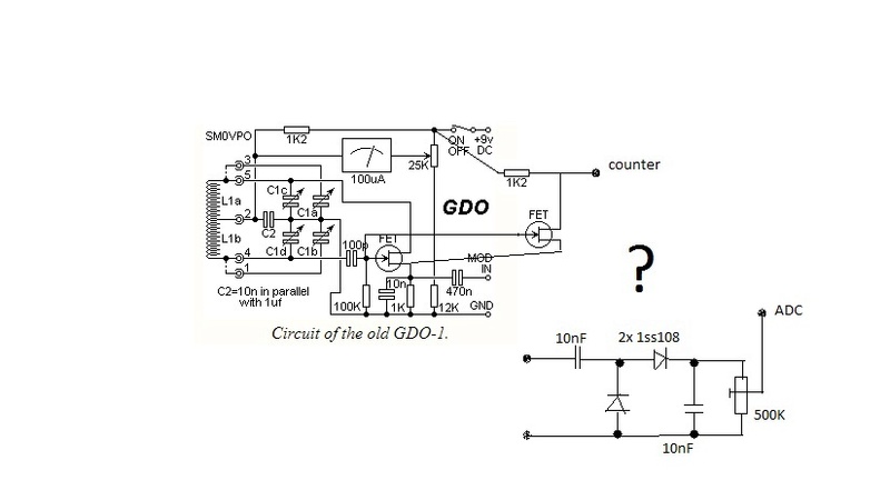
One possibility for measuring the GDO is to take a series resistor (47K ?) and 1nf capacitor from either the gate or the drain to the input of your counter.
With the GDO there is about 10v P-P at those two points so you should be able to sniff off a little RF without affecting the frequency (much).
Anyway, I want to wish you a very Happy New Year.
Interesting fact, today, everybody who is legally an adult (over 18) were born in the 1900's. All "minors" (under 18) were born in the 2000's.
Vdry best regards from Harry - SM0VPO
_________________
Everything in this world is either bacon, or it isn't bacon
They say that money cannot bring you happiness, but if you have it then you can always buy more bacon
admin- Admin
- Posts : 1144
Join date : 2012-11-24
Age : 72
Location : Märsta, Sweden -
Re: GRID DIP OSCILLATOR by Harry Lythall - SM0VPO question
![]() by zsolt Sat Dec 30, 2017 7:52 pm
by zsolt Sat Dec 30, 2017 7:52 pm
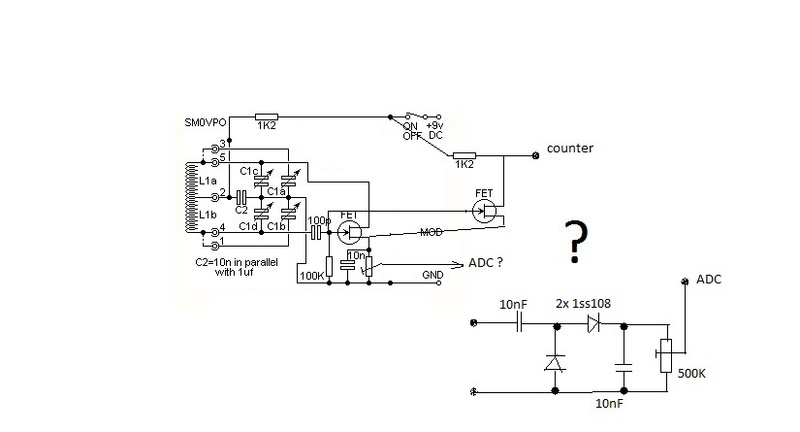
first of all best wishes for all . About the gdo 1 , since i'm using a self made frequency meter with 2x8 LCD i taught that i could display on the second row also the amplitude in a form of a bar graph. With this i could eliminate the microampermeter ( i used a magnetoelectric device which is not performing quite so well ) .
I have an analog pin left free, and i can use internal 1.2V reference for ADC if needed.I have no idea if it can work or not, but where would you connect the analog input (with respect to GND) in the GDO1 circuit, in order to do this ?
zsolt- Posts : 209
Join date : 2017-12-19
Re: GRID DIP OSCILLATOR by Harry Lythall - SM0VPO question
![]() by zsolt Sun Dec 24, 2017 4:46 pm
by zsolt Sun Dec 24, 2017 4:46 pm
it was a great time , and so fun . Actually i'm glad for having no computer back then .
zsolt- Posts : 209
Join date : 2017-12-19
Re: GRID DIP OSCILLATOR by Harry Lythall - SM0VPO question
![]() by Ivan Sun Dec 24, 2017 10:51 am
by Ivan Sun Dec 24, 2017 10:51 am
3,5 MHz (80 m) band is not free. It is one of the hamradio shortwave bands. There are five distinct frequencies inside that band reserved for foxhunting. The "foxes" are allowed to send certain CW patterns only - perhaps E, I, S, H and 5 (. .. ... .... .....).
BR Ivan
Ivan- Posts : 792
Join date : 2012-11-25
Age : 64
Location : Praha, Czechia
Re: GRID DIP OSCILLATOR by Harry Lythall - SM0VPO question
![]() by zsolt Sat Dec 23, 2017 7:16 pm
by zsolt Sat Dec 23, 2017 7:16 pm
zsolt- Posts : 209
Join date : 2017-12-19
Re: GRID DIP OSCILLATOR by Harry Lythall - SM0VPO question
![]() by Ivan Fri Dec 22, 2017 7:52 am
by Ivan Fri Dec 22, 2017 7:52 am
there is a central hamradio club in almost every country, and a governmentory radiocommunications regulator, too. You should get all the basic information on their webpages: hamradio bandplans, technical conditions (maximum radiated power, stability of frequency, spectrum purity,...), exams to pass etc. To build or purchase your own transmitter legally, you must have a license and a callsign from the regulator office.
BR from Ivan OK1SIP
Ivan- Posts : 792
Join date : 2012-11-25
Age : 64
Location : Praha, Czechia
Re: GRID DIP OSCILLATOR by Harry Lythall - SM0VPO question
![]() by zsolt Thu Dec 21, 2017 4:25 pm
by zsolt Thu Dec 21, 2017 4:25 pm
WOW !Ivan wrote:Hi Zsolt,
a range of a transmitter depends very much on its antenna, ground system, output power, ionosferic conditions and many many other things.
A HF CW transmitter with maximum legal power for hams can send its signal twice around the globe using ionosferic reflections.
A VHF /UHF CW transmitter with maximum legal power for hams can send its signal from Earth to Moon and get reflected it back.
VBR from Ivan
Where can i found this data ? about ham and max legal power ?
zsolt- Posts : 209
Join date : 2017-12-19
Re: GRID DIP OSCILLATOR by Harry Lythall - SM0VPO question
![]() by Ivan Thu Dec 21, 2017 3:07 pm
by Ivan Thu Dec 21, 2017 3:07 pm
a range of a transmitter depends very much on its antenna, ground system, output power, ionosferic conditions and many many other things.
A HF CW transmitter with maximum legal power for hams can send its signal twice around the globe using ionosferic reflections.
A VHF /UHF CW transmitter with maximum legal power for hams can send its signal from Earth to Moon and get reflected it back.
VBR from Ivan
Ivan- Posts : 792
Join date : 2012-11-25
Age : 64
Location : Praha, Czechia
Re: GRID DIP OSCILLATOR by Harry Lythall - SM0VPO question
![]() by zsolt Thu Dec 21, 2017 1:44 pm
by zsolt Thu Dec 21, 2017 1:44 pm
no method functioned or all my sample tags are bad . I think that for first i need a 100% functional tag . Then i'll try again .
Ps: how far could i transmit with a cw transmitter ?
zsolt- Posts : 209
Join date : 2017-12-19
Re: GRID DIP OSCILLATOR by Harry Lythall - SM0VPO question
![]() by Ivan Thu Dec 21, 2017 8:13 am
by Ivan Thu Dec 21, 2017 8:13 am
maybe you do not need an oscillator at all. If a coil produced a square pulse (switched DC in fact), the metal strips should start vibrating. Their vibration should be picked up by the same or another coil just after the pulse ends.
BR from Ivan
Ivan- Posts : 792
Join date : 2012-11-25
Age : 64
Location : Praha, Czechia
Re: GRID DIP OSCILLATOR by Harry Lythall - SM0VPO question
![]() by zsolt Wed Dec 20, 2017 7:39 pm
by zsolt Wed Dec 20, 2017 7:39 pm
the transformer coils let me go down to 56 kHz indeed ,just that i can't dip the 56 kHz RF tag's with that construction. We have the 8.2 MHz tags which can be verified with your first GDO perfectly because these tags are LC circuits . The 56 kHz tags are not LC , according to wikipedia: they have a strip of magnetostrictive, ferromagnetic amorphous metal and a strip of a magnetically semi-hard metallic strip, which is used as a biasing magnet (to increase signal strength) and to allow deactivation. These strips are not bound together but free to oscillate mechanically.

These give me some trouble to check .... for now i only got the idea to build an 56kHz oscillator and use it to attack an audio amp ( i have one with some TDA2... audio chip, that according to datasheet is not attenuating very much in that frequency range far as i remember ) Instead of speaker i'm willing to put an air wound coil to vibrate up the tag . Near the tag i will put a pick up coil connected to a scope . I believe that after i suddenly stop the amp, if the tag is good it will still vibrate a little to induce something in the pick up coil connected to the scope . All this are presumptions , i have no idea if this works like that , i'll do it anyway
Thanks and best wishes from me also !
zsolt- Posts : 209
Join date : 2017-12-19
Re: GRID DIP OSCILLATOR by Harry Lythall - SM0VPO question
![]() by admin Wed Dec 20, 2017 7:41 am
by admin Wed Dec 20, 2017 7:41 am
Great that you find so many projects interesting. At the moment I have several projects on the bench, but one big project needs a lot of time, and I am not able to have that time. Handicapped wife, Christmas, 24/7 callout etc. But they will come.
As regards the lower frequency limit of the GDO, there is no lower electrical limit. My original GDO covered 80kHz and I used a mains transformer coil to try lower limits. I had it down to much less than 1kHz. Unfortunately it was with the iron core, which made it useless as a dip meter, but it worked as an oscillator.
You could try getting two of these transformers. The 230V winding is on a pre-wound former, so you could strip them down and put the two 230V windings in series to get a ready-made VLF coil. Just a suggestion. You may have to use a parallel resistor to damp it a little to get a stable performance.
56kHz?? Here in Sweden they use 8.2MHz for the shop anti-theft alarms. I must confess to having a bit of fun with them, but as Maj-Lis says, men never grow up.

Good luck with the projects.
Very best regards from Harry - SM0VPO
PS - I am now getting e-mail post notifications :-) Don't know what the problem was, just went in the admin pages, switched OFF then switched ON again.
_________________
Everything in this world is either bacon, or it isn't bacon
They say that money cannot bring you happiness, but if you have it then you can always buy more bacon
admin- Admin
- Posts : 1144
Join date : 2012-11-24
Age : 72
Location : Märsta, Sweden -
Re: GRID DIP OSCILLATOR by Harry Lythall - SM0VPO question
![]() by zsolt Tue Dec 19, 2017 5:12 pm
by zsolt Tue Dec 19, 2017 5:12 pm
actually i found many interesting pages here and some things i would try out .. regarding the GDO , is it possible to go down to 56 kHz with this type of oscillator ? I'm checking RF anti-theft labels with it . (we buy them and print them )

zsolt- Posts : 209
Join date : 2017-12-19
Re: GRID DIP OSCILLATOR by Harry Lythall - SM0VPO question
![]() by admin Tue Dec 19, 2017 3:54 pm
by admin Tue Dec 19, 2017 3:54 pm
By the way, I have activated your account zsolt and you have all the permissions. Welcome to HHH SM0VPO forum. Hope you find a lot to interest you and thank you for participating.
Very best regards from Harry SM0VPO
_________________
Everything in this world is either bacon, or it isn't bacon
They say that money cannot bring you happiness, but if you have it then you can always buy more bacon
admin- Admin
- Posts : 1144
Join date : 2012-11-24
Age : 72
Location : Märsta, Sweden -
GRID DIP OSCILLATOR by Harry Lythall - SM0VPO question
![]() by zsolt1 Mon Dec 18, 2017 7:54 pm
by zsolt1 Mon Dec 18, 2017 7:54 pm
I would like to use a input pin (ex. timer0 clock input) with TTL level to get the frequency , what circuit should i search for ?
Thanks
zsolt1- Guest
Page 2 of 2 • 1, 2
» Arduino etc. (was: GRID DIP OSCILLATOR)
» PIC based DC/AC Mk-II (by Harry Lythall) suggestion
» Speech Processor by Harry Lythall - SM0VPO_Correction to overlay
» A question for Harry... if I can