Can Ivan and Glen please take a look at this page for me? (new project)


Re: Can Ivan and Glen please take a look at this page for me? (new project)
![]() by Ivan Mon Jun 07, 2021 8:30 pm
by Ivan Mon Jun 07, 2021 8:30 pm
Ivan- Posts : 793
Join date : 2012-11-25
Age : 64
Location : Praha, Czechia
admin likes this post
Re: Can Ivan and Glen please take a look at this page for me? (new project)
![]() by Ivan Wed Dec 16, 2020 7:45 am
by Ivan Wed Dec 16, 2020 7:45 am
I can add a single word only to your text: AMEN.
VBR from Ivan
Ivan- Posts : 793
Join date : 2012-11-25
Age : 64
Location : Praha, Czechia
admin likes this post
Re: Can Ivan and Glen please take a look at this page for me? (new project)
![]() by admin Tue Dec 15, 2020 10:12 pm
by admin Tue Dec 15, 2020 10:12 pm
As I wrote, you have not been very lucky, and the corona precautions complicating it.
I think we will all be happier when 2020 has finished. I has not been a good year. We had legal problems - lawyers insisting we do things that were not allowed due to lockdown, etc. We sold our Spanish house but were unable to get our belongings out, and the lawyers insisted the car (included in the sale) be tested, even though the government test stations were closed (non-essential).
Shouldn't have put the clocks back an hour in October - the year would have been an hour shorter.
But here's hope that you get better and that 2021 will be better for us all.
Best regards from Harry - SM0VPO
_________________
Everything in this world is either bacon, or it isn't bacon
They say that money cannot bring you happiness, but if you have it then you can always buy more bacon

admin- Admin
- Posts : 1144
Join date : 2012-11-24
Age : 72
Location : Märsta, Sweden -

Re: Can Ivan and Glen please take a look at this page for me? (new project)
![]() by Ivan Tue Dec 15, 2020 11:47 am
by Ivan Tue Dec 15, 2020 11:47 am
Hi Harry,Admin wrote:...
I am really sorry to hear about your misfortune, Ivan. You have not been very lucky with your health this past year, or so. You wrote that you slipped OUT of the tram. Do you mean that you landed in the road behind the tram?
You are lucky that you have no broken bones, but I do hope that you make a rapid recovery.
thank you for your sympathy. Yes, just two years ago my problems with backbone started. I am retired due to it and get salary refund from my insurance. I walk with crutches.
Two weeks ago I missed the edge of stairs in a tram (it was a 1960 type with a floor quite high above the rails) and ended lying outside, at the tram stop. Covid took place in it, too, as the respirator (compulsory now) blocked my view downside. I hurt my back, right hand and both knees. Fortunately, I feel better again.
VBR from Ivan
Ivan- Posts : 793
Join date : 2012-11-25
Age : 64
Location : Praha, Czechia
Re: Can Ivan and Glen please take a look at this page for me? (new project)
![]() by Ivan Tue Dec 15, 2020 11:28 am
by Ivan Tue Dec 15, 2020 11:28 am
thank you for a lot of material to study and to think about. Some of the antennas seem to be good mainly for UHF and uW bands, while other are designed for HF. I must say that I have doubts about their efficiency (they say up to 80%), e.g. that of coiled or meandlered wire. Some years ago I modelled a short dipole made of two wire meanders. Its VSWR looked O.K. , but its radiation efficiency was poor: the currents in neighbouring sections almost cancelled each other.
The topic of small antennas for HF still requires study and testing!
VBR from Ivan
Ivan- Posts : 793
Join date : 2012-11-25
Age : 64
Location : Praha, Czechia
Re: Can Ivan and Glen please take a look at this page for me? (new project)
![]() by Glenndk Thu Dec 10, 2020 9:23 pm
by Glenndk Thu Dec 10, 2020 9:23 pm
Another type of antenna is a metamaterial antenna - in this case a very short dipole coupled with a split ring resonator (SRR) by the close proximity (dipole decoration!).
The SRR is one type of a metamaterial resonator - it is just a resonator with a funny design! - two "C" (but any polygon shape will do) of e.g. copper in each other - one "C" is rotated 180 degrees.
The "C"s are the two coils and the close proximity of the "C"s is the two distributed capacitors. You can change the antenna resonance by exchanging the SRR (SRR ski lift system?) - or equip the short dipole with one SRR for each band - or maybe tuning the SRR - moving the two "C"s relative to each other - translation or rotating?:
Radiation properties of a split ring resonator and monopole composite:
http://www.fen.bilkent.edu.tr/~ozbay/Papers/154-07-bora-pssb.pdf
https://web.archive.org/web/20200510130659/http://www.fen.bilkent.edu.tr/~ozbay/Papers/154-07-bora-pssb.pdf
Quote: "...
And finally we estimated the efficiency as 42.88%. [at 3.62 GHz - should be much higher at HF ! ]
...
One of the promising properties of the SRR monopole composite is its size. Without considering the ground plane, one should have a λ/2 antenna size for efficient coupling and radiation. On the other hand, for our composite structure the antenna size was approximately λ/10. We can state that this antenna is electrically small; moreover, by modifying the SRR structure in terms of capacitor loading the antenna size could even be reduced to λ/40. This work will be addressed in another paper.
...
In conclusion, the monopole and SRR composite behaves like an electrically small antenna (λ/10) operating at the resonance frequency of the SRR.
..."
Electrically small split ring resonator antennas:
http://www.fen.bilkent.edu.tr/~ozbay/Papers/155-07-bora-jap.pdf
https://web.archive.org/web/20160320075000/http://www.fen.bilkent.edu.tr/~ozbay/Papers/155-07-bora-jap.pdf
More in danish:
https://da.wikipedia.org/wiki/Metamaterialeantenne
_________________
best regards,
Glenn / OZ1HFT
Glenndk- Posts : 114
Join date : 2017-01-06
Location : Copenhagen, Denmark -
Re: Can Ivan and Glen please take a look at this page for me? (new project)
![]() by Glenndk Thu Dec 10, 2020 8:18 pm
by Glenndk Thu Dec 10, 2020 8:18 pm
Admin wrote:
I have been looking at this thread for over a week, and I have been following ALL the links you both posted.
I have been doing yet more experiments with my multiband antenna and I have found that using a base loading coil gives a good match, but it also increases the Q factor and reduces signal strength compared to a full dipole. A a result it is not possible to cover all the band at 3.5MHz, and at 7MHz the bandwidth is not as wide as a straight dipole.
...
A 3.7MHz fold-back dipole, however, was not so succesful. I could get a resonance but needed 25 metres of wire in each half. Than meant 5 + 3 + 3 + 3 + 3 + 3 + 3 + 2m dangling, which meant the dipole went from mast to guy seven ties, and it looked BIG.
---
1 - using coils
2 - using fold-back
3 - getting down to 3.5MHz by a different method (without coils)
...
Very best regards from Harry - SM0VPO
Hi all
Here is yet another way to make a dipole shorter. I think that a loading coil makes a dipole narrow bandwidthwise. Use this MLA circular winding one-way and another-way changing coils. Make the diameter larger or use more winding in each "coil" until resonance at 5,4meter+5,4meter.
If Baker et al can make a "10 meter dipole" into a 2x1 meter "Toroidal Helical Antenna" - you should be able to make a "40 meter dipole" into a (straight?) 2x4 meter "Toroidal Antenna". You might use a number of cut up metal slinkys - just pull or push to make the antenna resonance at 80 meter band? (but do not let children see you destroying the slinkys christmas eve) The antenna looks like an alien inspired antenna:
New short HF antennas for the 20 meter [or 80 meter!] band contained in one cubic meter [4^3=64 cubic meter?], MLA-like:
2014, New Design Methodology for Electrically Small HF Antenna, Baker:
https://web.archive.org/web/20171101224438/http://hcac.hawaii.edu/pdfs/aps2014/baker.pdf
Quote: "...
Fig. 2. Toroidal Helical Antenna [<- best? - shortest wire length]
...
The total height of the antenna is less than one meter
..."
-
Performance of a Meandered Line as an Electrically Small Transmitting Antenna:
http://www.ittc.ku.edu/~callen/active_antennas/Warnagiris1998TAPpp1797-1801.pdf
https://web.archive.org/web/20170808083112/http://www.ittc.ku.edu/~callen/active_antennas/Warnagiris1998TAPpp1797-1801.pdf
Quote: "...
Folding offers the possibility of reducing the size of an antenna while still maintaining a high-radiation resistance at resonance.
...
A dipole 3 ft in overall length was fabricated having a first resonance center frequency of 14.2 MHz. VSWR bandwidth of 2 : 1 was measured over 6.5% of the center frequency (see Fig. 5). When tested for radiation efficiency using the Wheeler method, this antenna exhibited a radiation efficiency of 80% [11]. This is much higher than would be expected for a loaded dipole of 0.05 wavelengths in overall length.
..."
-
best regards,
Glenn / OZ1HFT
Glenndk- Posts : 114
Join date : 2017-01-06
Location : Copenhagen, Denmark -
Re: Can Ivan and Glen please take a look at this page for me? (new project)
![]() by admin Wed Dec 09, 2020 9:39 pm
by admin Wed Dec 09, 2020 9:39 pm
Thank you for the words of encouragement. I am really motivated because I now have an RF-quiet garden, albeit small. I really want 7MHz to 29MHz and too put out a decent signal.
Today's QRP seems to be 50 Watts or so, as most stations to which I speak nowadays always seem to have 400 Watts or more. I do not want more power, now that I have got 100W. That is my ceiling, but I will not use it under "normal" conditions. I think it is better to put 6dB more antenna in the air, and increase the height by another 4dB.
Thanks to you guys I have got loads of ideas and suggestions, then been able to do a lot of experiments from type of wire, ribon wire, folded, even wire-size. By using MW broadcast stations (Radio Romania 0n 7.205MHz, BBC-WS on 12.095 etc) I can measure (depending on conditions). At the moment I have two masts in the garden, but one of them has to come down at the weekend (and the other painted black).
Now I have finalised the design I will use. Today I spent another hour in the attic of the GIC (see google maps below)
https://www.google.se/maps/place/GIC+Coffee/@59.5629439,17.8832581,595m/data=!3m2!1e3!4b1!4m5!3m4!1s0x465fbd3cf7025e05:0x177ad036fc60fcc2!8m2!3d59.5629412!4d17.8854468
I am laying the diploes on the floor. The attic is the only place I can find where I can lay 7 cables on the floor without other workers tramping on them all the time.
When I have finished there is even enough space for me to connect the full dipole(s) to the balun, hang them, and watch them on a professional ($50,000) analyser. Then I can tune the dips in the VSWR while still indoors. I will see if I can get a photo taken, but ordinary cameras are not allowed in there. I can get QA to take a picture using their encrypted camera (pictures must be approved by management/security before being released).
I am really sorry to hear about your misfortune, Ivan. You have not been very lucky with your health this past year, or so. You wrote that you slipped OUT of the tram. Do you mean that you landed in the road behind the tram?
You are lucky that you have no broken bones, but I do hope that you make a rapid recovery.
All my very best regards from Harry - SM0VPO
_________________
Everything in this world is either bacon, or it isn't bacon
They say that money cannot bring you happiness, but if you have it then you can always buy more bacon
admin- Admin
- Posts : 1144
Join date : 2012-11-24
Age : 72
Location : Märsta, Sweden -
Re: Can Ivan and Glen please take a look at this page for me? (new project)
![]() by Ivan Wed Dec 09, 2020 2:27 pm
by Ivan Wed Dec 09, 2020 2:27 pm
you did a lot of good work. Congratulations!
i was tempted to do some experiments with the ribbon cable in my garden, too, but things went wrong. "If you want to make the God to laugh, tell him you plans." While shopping for Xmas, I slipped on stairs of a tram and fell out. I hardly do several steps across my room now. No bone seems to be broken fortunately. I hope I will cure fast. You did those experiments in the meantime. Thank you once more!
VBR from Ivan
Ivan- Posts : 793
Join date : 2012-11-25
Age : 64
Location : Praha, Czechia
admin likes this post
Re: Can Ivan and Glen please take a look at this page for me? (new project)
![]() by admin Mon Dec 07, 2020 11:18 pm
by admin Mon Dec 07, 2020 11:18 pm
I have been doing yet more experiments with my multiband antenna and I have found that using a base loading coil gives a good match, but it also increases the Q factor and reduces signal strength compared to a full dipole. A a result it is not possible to cover all the band at 3.5MHz, and at 7MHz the bandwidth is not as wide as a straight dipole.
Ivan / Glenn:
I was particularly interested in your suggesions and the links for the ribbon cable antenna. Here in Sweden the ribbon cable is quite expensive, so I used 10/0.7mm hookup wire and some food-bag sealers so that I could have my seven dipoles.
Yes, it worked, but the close proximity of the dipoles does affect the tuning. In one of the article you linked the author stated this, and his solution was to leave the last 500mm or 1000mm dangling so that the effect is minumised. That works, but I also found that the plastic on the dipoles close to the feed-point had melted and the geometry changed. The plastic bag-sealer had become fused to the wire insulation. I was only running 100 Watts.
I also tried a "lash-up" to fold-back the 7MHz dipole, and as per the article I had to increase the length quite a lot. Almost 2 metres using the home-made ribbon! Then I went back to the plastic spacers and found that each 1/2 of the dipole were 5m + 2.2m back, then 2.2m forward again, plus 1000mm dangling, it worked perfectly.
Using the ribbon fold-back and using the spaced fold-back simultaneously I found that there was a measureable difference in signal strength. The spaced fold-back was better by about 6dB (7.205MHz AM BC station for reference).
My conclusion is that the ribbn method will get a good VSWR, but OTA there is a 6dB better signal having the fold-back spaced at 4.666cm (or more) intervals. The fold-back method also gives a wider-bandwidth than the oroginal method using coils.
A 3.7MHz fold-back dipole, however, was not so succesful. I could get a resonance but needed 25 metres of wire in each half. Than meant 5 + 3 + 3 + 3 + 3 + 3 + 3 + 2m dangling, which meant the dipole went from mast to guy seven ties, and it looked BIG.
Glynn,
I saw that suggestion for a single tuneable antenna and I really like that. I think thta it could be really easily implemented using a straight 5m + 5m dipole, but have each end of the dipole on a spool, like a YoYo (remember the yoyo?). That way, you pull the cord, the yoyo rolls up the dipole from the end inwards, and the counter-weight rises.
That way you have a fixed feed-point without any sliding contacts. Your idea was a really good spark and I think it can be developed. The only complication would be the motor/winch needed to pull the cord from the yoyo, especially in a Swedish winter when there are 18'C and 500mm of snow on the ground.
But there have been some really great ideas. I am sorry I have not spent a lot of time on the board. I have been working a lot, and I was also working last weekend, so I prioritised experiments over computer.
I have decided to go ahead with:
1 - Extending my mast to 9m using TV-mast pipe, 38mm Dia.
2 - Painting the mast black so reduce the visibility for the kommun guys
3 - Having the guy-ropes only at 4m height so that only the black pole pokes above the bushes
4 - Dyed the guy ropes black (and my fingers due to leaky rubber gloves)
5 - 6 dipoles using black wires; 29MHz, 27MHz, 21MHz, 18MHz, 14MHz and 7MHz (5 + 2.2 + 2.2 + 1m dangling)
6 - 1KW 1:1 balun
7 - Bird table on the top (no kommun max height restriction for a bird table)
When I get everything on the air, then I will see about building a second alternative, so I can hoist up one or the other. The second antenna will be the yoyo, variable length antenna. The only problem with the yoyo is that with my available space the lowest band I can have is 20m.
My multiband dipole article will be divided:
1 - using coils
2 - using fold-back
3 - getting down to 3.5MHz by a different method (without coils)
Very best regards and thankyou VERY much gentlemen for all the ideas, links and suggestions. It all makes fantastic reading and really thought-provoking.
I spent my lunch-break at work today in the workshop, drilling plastic tubes for the fold-back multiband (7MHz and above). Tomorrow I will drill another 6 spacers and start cabling it up. I will be using 2mm Diameter, multi-strand power cable. Extra $25 but I may be able to get a couple of dB more.
Finally, one point.
I have got my Christmas present from Maj-Lis - a brand-new Icom IC-7300. The FFT and DSP enable me to hear crystal clear, stations that I could hardly detect with my FT-101ZD. That is great, BUT those stations can rarely hear me unless they, too, have DSP. I was listening at 5AM last night and heard stations from over the Atlantic. 100% copy, but they could not hear me.
Very best regards from Harry - SM0VPO
_________________
Everything in this world is either bacon, or it isn't bacon
They say that money cannot bring you happiness, but if you have it then you can always buy more bacon
admin- Admin
- Posts : 1144
Join date : 2012-11-24
Age : 72
Location : Märsta, Sweden -
Re: Can Ivan and Glen please take a look at this page for me? (new project)
![]() by Ivan Fri Nov 27, 2020 10:34 am
by Ivan Fri Nov 27, 2020 10:34 am
it is an interesting idea. Connecting both arms together can be accomplished e.g. by making a double bobbin from brass. The harder task is to maintain fixed mutual position of both dipoles outdoors (in wind etc.)
VBR from Ivan
Ivan- Posts : 793
Join date : 2012-11-25
Age : 64
Location : Praha, Czechia
Re: Can Ivan and Glen please take a look at this page for me? (new project)
![]() by Glenndk Thu Nov 26, 2020 8:35 pm
by Glenndk Thu Nov 26, 2020 8:35 pm
Ivan wrote:Hi,
here is an idea how to make a tunable, no ATU, no resistor HF antenna. It can be hung up as a dipole or inverted V. Each leg should be 7,5 m long to cover bands from 10 to 60 MHz.
black line - non-insulated stranded wire
blue line - polypropylene rope
1 - four nylon bobbins on the same axle
2 - motor with gearbox
3 - pulleys
4 - sliding ohmic contacts
5 - spring retaining mechanical tension, or
6 - weight
7 - 1:1 balun
8 - coax feeder
The length of exposed wires can be set as required. The really hard point is how to keep the sliding contacts #4 working in any weather and under corrosion.
VBR from Ivan
Hi Ivan
You do not need the sliding contacts, if you make a dipole of 7,5 m - parallel (about 5 cm distance?) to your two variable lengths legs. But the two variable lengths legs must be electrical connected together - they then form a parasitic element. The HF will be radiated much more from the parasitic element, that is in resonance with the delivered HF energy.
Both the dipole of 7,5 m and the parasitic element, might have meander line diversions?
_________________
best regards,
Glenn / OZ1HFT
Glenndk- Posts : 114
Join date : 2017-01-06
Location : Copenhagen, Denmark -
Re: Can Ivan and Glen please take a look at this page for me? (new project)
![]() by Ivan Tue Nov 24, 2020 9:36 pm
by Ivan Tue Nov 24, 2020 9:36 pm
exactly, I had in mind the shape of the wire on Harryś antenna when I mentioned "a meander". It is not extremely efficient, but probably it is better than a short antenna with bottom loading coil.
What capacitors do you speak about in the next sentences? I know MLA = Magnetic Loop Antennae, but they use one capacitor only. Very big RF current flows through the capacitor. You probably mean something else type of antenna...
VBR from Ivan
Ivan- Posts : 793
Join date : 2012-11-25
Age : 64
Location : Praha, Czechia
Re: Can Ivan and Glen please take a look at this page for me? (new project)
![]() by Glenndk Tue Nov 24, 2020 8:00 pm
by Glenndk Tue Nov 24, 2020 8:00 pm
Please also consider using two of these SM0VPO antennas balanced?:
http://sm0vpo.altervista.org/antennas/balcant2.htm
You could extend the "16 lengths" to 5,4 meters (then only 8-10 lengths?) boths ways?
Please note the wise quote: "...
Please note that this antenna idea is also governed by "Harry's Law" of coils:
* You cannot wind coils like me and I cannot wind coils like you.
* Coil-winding data is a constant that varies from person-to-person.
This means that it may NEED some adjustment in your own environment, depending upon proximity of other artifacts, humidity, groundplane efficiency and even the colour of the flag you have fitted to the top of the original 14MHz pole.
..."
-
Maybe only the "big" MLA (meander line antenna) should be used in each half; of e.g. 4 lengths (8 lengths (maybe more) if 160 meter should be covered) combined with capacitor e.g. from lengths to the feed point to make it broadband. I have absolutely no idea what the capacitances should be and how high capacitor voltage would be needed?
Maybe:
n=160/4/5,4 ca.= 8 lengths in each arm (4 back and forth) (might need more e.g. 16)
160 meter; the capacitors should all have high reactances. (only one connection directly to feed) (at 160 meter)
80 meter; one capacitor every 1/2 wavelength MLA (1/2 wavelength but connected each 1/4 wavelength) (including 1 directly) should have relatively low reactance. The rest should all have high reactances. (at 80 meter)
60 meter; one capacitor every 1/2 wavelength MLA (including 1 directly) should have relatively low reactance. The rest should all have high reactances. (at 60 meter)
40 meter; one capacitor every 1/2 wavelength MLA (including 1 directly) should have relatively low reactance. The rest should all have high reactances. (at 40 meter)
20 meter; (separate 2 x 5 meter? Fat with two wires connected together in the far end - to make it more broadbanded?)
17 meter...15 meter... (separate 2 x 4 meter? Fat with two wires connected together in the far end - to make it more broadbanded?)
12 meter... (separate 2 x 3 meter? Fat with two wires connected together in the far end - to make it more broadbanded?)
11 meter...
10 meter; one capacitor every 1/2 wavelength MLA (not possible? including 1 directly) (separate 2 x 2.5 meter? Fat with two wires connected together in the far end - to make it more broadbanded?) should have relatively low reactance. The rest should all have high reactances. (at 10 meter)
With a lot of relays and 1,2,4,8... capacitors - and a HF-antenna analyser you should try every combination to find the right capacitor values once and for all :-) It is "only" 256^8 or 256^16 combinations, when using 8 capacitors per length ends (8 or 16) :-)
Ivan; surprise - it could be a broadband antenna without a resistor and heat sink :-)
-
Performance of a Meandered Line as an Electrically Small Transmitting Antenna:
http://www.ittc.ku.edu/~callen/active_antennas/Warnagiris1998TAPpp1797-1801.pdf
https://web.archive.org/web/20170808083112/http://www.ittc.ku.edu/~callen/active_antennas/Warnagiris1998TAPpp1797-1801.pdf
Quote: "...
Folding offers the possibility of reducing the size of an antenna while still maintaining a high-radiation resistance at resonance.
...
A dipole 3 ft in overall length was fabricated having a first resonance center frequency of 14.2 MHz. VSWR bandwidth of 2 : 1 was measured over 6.5% of the center frequency (see Fig. 5). When tested for radiation efficiency using the Wheeler method, this antenna exhibited a radiation efficiency of 80% [11]. This is much higher than would be expected for a loaded dipole of 0.05 wavelengths in overall length.
..."
https://devzone.nordicsemi.com/question/12274/definitive-guide-for-meander-pcb-antenna/
Quote: "...
It can be a little tricky to design a meander antenna, because it radiates from the corners; when designing a meander antenna you want to make sure that the signals radiated from the corners result in construvtive interfernce.
..."
Last edited by Glenndk on Thu Nov 26, 2020 8:48 pm; edited 23 times in total
_________________
best regards,
Glenn / OZ1HFT
Glenndk- Posts : 114
Join date : 2017-01-06
Location : Copenhagen, Denmark -
Re: Can Ivan and Glen please take a look at this page for me? (new project)
![]() by Glenndk Tue Nov 24, 2020 7:30 pm
by Glenndk Tue Nov 24, 2020 7:30 pm
Especially from 30:49-33:00 the inverted V is actually omnidirectional - and from 56:10-59:30 "half-square" (never heard of it before) vertical polarised - but no ground loss no groundplane sounds appealing and low angle radio transmission; but has be 1/4 wavelength high and be 1/2 wavelength long horizontally - and then another 1/4 wavelength high down to just above ground level:
Everything you always wanted to know About Antennas (but were afraid to ask) || Frank Rutter K3AW:
https://www.youtube.com/watch?v=LEigIMS6bo4
_________________
best regards,
Glenn / OZ1HFT
Glenndk- Posts : 114
Join date : 2017-01-06
Location : Copenhagen, Denmark -
Re: Can Ivan and Glen please take a look at this page for me? (new project)
![]() by Ivan Tue Nov 24, 2020 2:02 pm
by Ivan Tue Nov 24, 2020 2:02 pm
here is an idea how to make a tunable, no ATU, no resistor HF antenna. It can be hung up as a dipole or inverted V. Each leg should be 7,5 m long to cover bands from 10 to 60 MHz.
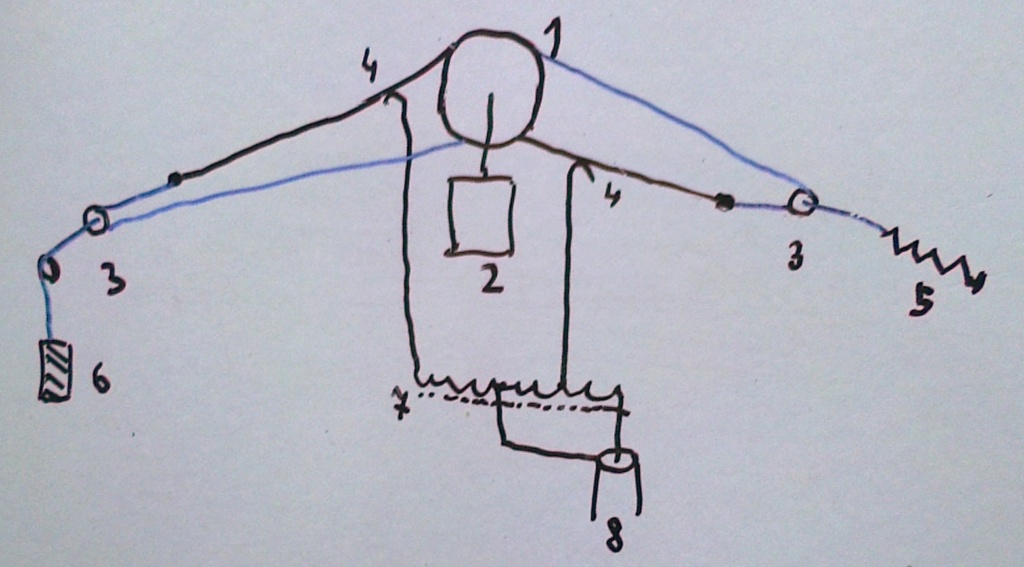
black line - non-insulated stranded wire
blue line - polypropylene rope
1 - four nylon bobbins on the same axle
2 - motor with gearbox
3 - pulleys
4 - sliding ohmic contacts
5 - spring retaining mechanical tension, or
6 - weight
7 - 1:1 balun
8 - coax feeder
The length of exposed wires can be set as required. The really hard point is how to keep the sliding contacts #4 working in any weather and under corrosion.
VBR from Ivan
Ivan- Posts : 793
Join date : 2012-11-25
Age : 64
Location : Praha, Czechia
Re: Can Ivan and Glen please take a look at this page for me? (new project)
![]() by Glenndk Mon Nov 23, 2020 7:48 pm
by Glenndk Mon Nov 23, 2020 7:48 pm
Ivan wrote:Hi Glenn,
...
Some hams tend to do it this way: an ATU just adjacent to the TRX, then a long coax feeding a short antenna. It is a wrong way!
...
I like e.g. the solution, where a switched length of 450 ohm ladder line matches one dipole to a coax feeder. None ATU is used, one wideband balun only.
VBR from Ivan
Actually I would like the ATU after the antenna, and the ATU z-bridge must placed between the antenna and transmission line. The TC2M-antenna has two ports, so it should be possible.
And yes, a switched length transmission line ATU is a lot less lossy:
W5DXP's No-Tuner, All-HF-Band, Horizontal, Center-Fed Antenna:
https://web.archive.org/web/20191219204049/http://www.w5dxp.com/notuner/notuner.htm
Better yet - a broadband antenna and no ATU...?
_________________
best regards,
Glenn / OZ1HFT
Glenndk- Posts : 114
Join date : 2017-01-06
Location : Copenhagen, Denmark -
Re: Can Ivan and Glen please take a look at this page for me? (new project)
![]() by Ivan Mon Nov 23, 2020 7:41 pm
by Ivan Mon Nov 23, 2020 7:41 pm
coils tend to be lossy on HF. A long piece of relatively thin copper wire exhibits quite big resistance, straight or coiled. And a few dB of losses almost cannot be heard at the receiver, it is less than 1 S point. Nevertheless I still feel a purely reactive antenna ev. lengthened with high-Q loading coils to be a better solution.
Some hams tend to do it this way: an ATU just adjacent to the TRX, then a long coax feeding a short antenna. It is a wrong way! A two wire ladder line would be better than a coax in such cases. Matching and eventual balancing / unbalancing should be performed between the antenna and RF line, at least in a rough form.
I like e.g. the solution, where a switched length of 450 ohm ladder line matches one dipole to a coax feeder. None ATU is used, one wideband balun only.
VBR from Ivan
Ivan- Posts : 793
Join date : 2012-11-25
Age : 64
Location : Praha, Czechia
Re: Can Ivan and Glen please take a look at this page for me? (new project)
![]() by Glenndk Mon Nov 23, 2020 5:03 pm
by Glenndk Mon Nov 23, 2020 5:03 pm
Ivan wrote:Hi, Glenn,
I am full of doubts about efficiency of any antenna, which contains a resistor. I may be wrong, of course.
Answer:
You are not alone. Almost every other radio amateur get ticks, when an antenna contains a power resistor with a BIG heat sink :-)
Ivan wrote:
When we introduce a resistor into the antenna design, it will always burn a part of RF power into heat.
...
This is very bad when transmitting.
VBR from Ivan
Answer:
At the lower part of HF, it does not matter - especially if it is a horisontal antenna, they typically are only a few percent efficient. :-)
Source:
This horizontal polarised broadbanded TWA-antenna only radiates e.g. 0,44% (-23dB) as radio waves at 1,8MHz with 10 meter wire in 10 meters height:
http://web.archive.org/web/20150420080125/http://www.rcwa.org/Training/Wire_Antennas_10_160.pdf
Even with 23 meter wire in 40 meters height, only radiates 14% (-8,5dB) as radio waves.
The resistor in the 10 meter high TC2M-antenna are almost only used below 7MHz. At 1.9MHz the TC2M-antenna is 50% (-3dB) efficient, so about 50% converted to heat in the resistor.
But the TC2M-antenna is only (10 meter/160 meter) = 1/16 wavelengths long at 1.9MHz - so an efficiency of 50% is very good.
Another feature of the resistor is, that the TC2M-antenna is made broadbanded:
A new design of broadband HF vertical antenna:
http://www.tc2m.info/TC2M%20HF%20Vertical%20G8JNJ.pdf
Backup:
http://web.archive.org/web/20150529061427/www.tc2m.info/TC2M%20HF%20Vertical%20G8JNJ.pdf
Quote: "...
So by combining the best aspects of ‘fat’ cage antenna and a Terminated Folded antenna, it is possible to achieve a very wide instantaneous bandwidth and good efficiency, without the need for a tuneable antenna matching unit.
...
Impedance of terminating load – this determines the overall flatness of SWR curve across whole frequency range, especially the maximum SWR at the low frequency end of the operational bandwidth (less than 1/4 wave), but also the efficiency at LF due to the amount of power absorbed by the terminating load.
...
The low ‘Q’ broadband nature of the design means that it is not particularly susceptible to interaction with nearby objects. This makes it ideal for use in urban environments.
...
If an overall length of 10m is chosen, it is possible to achieve a usable operating bandwidth of 1.5MHz to 70MHz, along with good overall radiation efficiency throughout most of the frequency range.
...
Many engineers will naturally express concern about deliberately adding resistive loss into an antenna system. However, unwanted losses occur in all practical antennas. This can be through resistive or dielectric losses in cables, conductors, ground systems, matching networks and tuners.
...
This graph in Figure 16 shows the actual measured RF power being dissipated in the terminating load relative to the applied RF input power. This is expressed as a ratio in dB relative to input power at various operating frequencies.
...
[Note this!:]
Note that the measured performance at the lower end of the frequency range is actually better than the modelled values. This is not an error.
[]
The most likely explanation is that the system losses of the cage antenna, tuner and ground resistance are worse than calculated.
[]
[Note this!:]
So by comparison the TC2M results seem better than would perhaps be expected.
[]
This is not untypical of electrically short antennas on the LF band, as ground and tuner losses can be significant due to the low resistive and high capacitive value of feed impedance encountered with such designs.
[]
[Note this!:]
These are quite often not noticed by operators unless measurements can be taken, or comparisons made with other antennas.
..."
Please note how he almost braggs about how "good" a roller coil in ATUs is to "burn" HF-energy, when the ATU must tune short antennes - with respect to the wavelength - in the example 75% of the power is lost! (-6dB) :-) :
Impedance Matching. Part 3: L-Network Solutions. By David Knight G3YNH:
http://www.g3ynh.info/zdocs/z_matcing/part_3.html
Citat: “…One issue that will be noted is that the AMU [Antenna Matching Unit=ATU] efficiency is low when the antenna is electrically short. The lost power is also dissipated almost entirely in the [ATU] inductor. Before dismissing the situation as hopeless however; it should be observed that a good roller coil is perfectly capable of dissipating 50 W continuously, and it takes only about 5 W of radiated power at the low end of the HF spectrum to effect NVIS communications within a radius of about 1000 km. With an AMU efficiency as low as 25%, a 100 W SSB transmitter will still deliver 25 W PEP to the antenna. The peak matching-network loss in that case will be 75 W, but the average loss will be about 25 W. Hence the coil will get quite hot, but it is not likely to be damaged by a typical short-wave transceiver...”
Glenndk- Posts : 114
Join date : 2017-01-06
Location : Copenhagen, Denmark -
Re: Can Ivan and Glen please take a look at this page for me? (new project)
![]() by Ivan Mon Nov 23, 2020 10:51 am
by Ivan Mon Nov 23, 2020 10:51 am
I am full of doubts about efficiency of any antenna, which contains a resistor. I may be wrong, of course.
The power, presented by a TX to an antenna, splits to three parts: one part, represented by "radiation resistance", is radiated into space; the other part is turned into heat; the last part is reflected back to the TX. We want most of the power to be radiated. If an antenna contains reactive elements only (there is no expressed resistance in the form of a resistor), the amount of power turned into heat is small, as it is caused by parasitic resistances only. The VSWR expresses the ratio between the radiated and reflected part of power in this case.
When we introduce a resistor into the antenna design, it will always burn a part of RF power into heat. This way we can obtain a device, which reflects no power, i.e. it has perfect wideband VSWR, but radiates poorly. An extreme example is a good dummy load, which has VSWR = 1:1 across all its working band, but radiates nothing.
One can object, that a resistor may burn no power under certain circumstances. Well, a resistor burns no power, when there is no voltage on it. It can be replaced with a short in such case. It burns no power, when no current flows through it. It can be replaced with an open circuit in that case. And it burns no power, when the phase shift between voltage and current is exactly 90 deg, which can be hardly fulfilled across a wide frequency band. So an antenna employing a resistor is a bit weird for me.
Antennas with a resistor inside work "somehow". They trade their efficiency for being wideband. This is not so bad with RX antennas, because modern receivers are very sensitive. This is very bad when transmitting.
VBR from Ivan
Ivan- Posts : 793
Join date : 2012-11-25
Age : 64
Location : Praha, Czechia
Re: Can Ivan and Glen please take a look at this page for me? (new project)
![]() by Glenndk Sun Nov 22, 2020 9:03 pm
by Glenndk Sun Nov 22, 2020 9:03 pm
Admin wrote:
Hi Glenn,
Yes, please. Any and all comments and suggestions are really welcome.
Do you have a radical broadband suggestion?
...
So what radical antenna had you in mind?
BR Harry - SM0VPO
Last one (for now :-) ):
http://hflink.com/antenna/#BBTD
http://hflink.com/antenna/#BBTDROOF
Backup:
https://web.archive.org/web/20180216034751/http://hflink.com/antenna/#BBTD
-
Search used:
Broadband butterfly terminated dipole (BBTD):
https://www.google.com/search?q=broadband+terminated+butterfly+dipole
_________________
best regards,
Glenn / OZ1HFT
Glenndk- Posts : 114
Join date : 2017-01-06
Location : Copenhagen, Denmark -
Re: Can Ivan and Glen please take a look at this page for me? (new project)
![]() by Glenndk Sun Nov 22, 2020 8:50 pm
by Glenndk Sun Nov 22, 2020 8:50 pm
Admin wrote:
Hi Glenn,
Yes, please. Any and all comments and suggestions are really welcome.
Do you have a radical broadband suggestion?
...
So what radical antenna had you in mind?
BR Harry - SM0VPO
Here is another simple wideband HF antenna covering 160-10 meter:
End fed:
http://www.dc4fs.de/VK6.pdf
Backup:
https://web.archive.org/web/20160828084916/http://www.dc4fs.de/VK6.pdf
The antenna is known in Australia for VK6-broadband. The two constructers are VK6IM and VK6YX.
Mayby the length can be shrunk from 23 meter to 11 meter by some MLA trick?
Please note that the T200-2 core is a bad choice. I should be a FT-240-61 with 12 bifilar windings (maybe two for 100W depending on the swr?) ( source: 4:1 http://web.archive.org/web/20170219191746/http://www.g8jnj.net/balunsandtuners.htm )
-
Balanced version:
Broadband Dipole 2MHz to 30MHz with no ATU:
Broadband "Travelling Wave" Dipole.
Based on a design by Dr. R.J.F. Guertier and G.E. Collyer, (1974 address) Antenna Engineering Australia (Pty) Ltd., Melbourne
http://www.paws.dircon.co.uk/draka.htm
https://web.archive.org/web/20140326031448/http://www.paws.dircon.co.uk/draka.htm
http://www.dxzone.com/cgi-bin/dir/jump2.cgi?ID=22145
Last edited by Glenndk on Sun Nov 22, 2020 9:12 pm; edited 4 times in total
Glenndk- Posts : 114
Join date : 2017-01-06
Location : Copenhagen, Denmark -
Re: Can Ivan and Glen please take a look at this page for me? (new project)
![]() by Glenndk Sun Nov 22, 2020 7:52 pm
by Glenndk Sun Nov 22, 2020 7:52 pm
Admin wrote:
Hi Glenn,
Yes, please. Any and all comments and suggestions are really welcome.
Do you have a radical broadband suggestion?
...
So what radical antenna had you in mind?
BR Harry - SM0VPO
When I saw your multi-dipole with all its parallel wires, I thought of the TC2M-antenna:
https://sm0vpo.forumotion.com/t228-indoor-tc2m-g8jnj-broadband-shortwave-antenna-tested#1159
It should also work as a balanced antenna with two TC2M arms. (2 x 5.4 meters). The arm length is not critical, but longer is better for lower frequencies. (The 10 meter vertical TC2M arm version radiates 50% at 1.8MHz according to the G8JNJ measurements. And higher efficiencies at higher frequencies. At 7MHz the radiation efficiency approaches 80-100%)
Each arm need 5 or more round spacers (one for each meter TC2M-antenna). A center wire (terminated by 450ohm) - and mayby 6 wires around the center in a circle radius of 30cm. (fed by 170ohm) (see G8JNJ description)
Each arm needs an unbalanced feed with 170ohm (approx z 4:1 to 50ohm) (or 340ohm balanced).
Each arm needs an unbalanced dummyload of 450ohm (z 9:1 to 50 ohm dummyload) (or 900ohm balanced).
The two arm should have signals fed with opposite phase.
I you use FT240-61 (or FT140-61 for QRP) for the transformers, it should cover 1.8-52MHz (slightly higher loss/NF at 70MHz).
Because the antenna is horizontal, it will also be inefficient at 14MHz and higher. But should be more efficient than a T2FD-antenna with equal length (halfing losses). A T2FD-antenna is inefficient because the "return wire" negative phase current is visible in the far field. (the TC2M-antenna center "return wire" negative phase current is NOT visible in the far field by design, because of the 6 wires that make a sort of Faraday "cage/tube" around the center wire)
Source:
This horizontal polarised broadbanded TWA-antenna only radiates e.g. 0,44% as radio waves at 1,8MHz with 10 meter wire in 10 meters height:
http://web.archive.org/web/20150420080125/http://www.rcwa.org/Training/Wire_Antennas_10_160.pdf
Even with 23 meter wire in 40 meters height, only radiates 14% as radio waves.
-
I am trying to cross/merge the TC2M-antennas with the MLA (meander line antenna) so the antenna might radiate more below 14MHz. I got the idea this morning, but it has not been tested yet. I almost have all the components for the antenna. I want to use it indoor and vertically. But I do not have the spacers - need to be low-loss plastic and light, need many spaces to hold the MLA "wire diversions" in a form that is true to the TC2M-antenna design.
Last edited by Glenndk on Sun Nov 22, 2020 9:12 pm; edited 1 time in total
_________________
best regards,
Glenn / OZ1HFT
Glenndk- Posts : 114
Join date : 2017-01-06
Location : Copenhagen, Denmark -
Re: Can Ivan and Glen please take a look at this page for me? (new project)
![]() by admin Sun Nov 22, 2020 6:56 pm
by admin Sun Nov 22, 2020 6:56 pm
Densil wrote:hi harry. in the article you keep refering to 5.4 metres for 14mhz quarterwave. I think that can be misleading.
The 20m band is from 14.0 to 14.35, so the band center is (14 + 14.35) / 2 = 14.175.
To take into account your length should be 97.5% of the calculated - ie
(75 * 0.975) / 14.175 = 5.15875 metres. You assumption is 25cm too long.
Am i right?
/D
Hello Densil,
You have not been here for a long time.
When you are experimenting with antennas, always make them longer than you need. Then you can coil them to make them shorter. Uncoil them if you want to adjust a bit longer. It is a but difficult to uncut if you need to add a few cm.
Have I answered your question?
Are you interested in small space antennas? Please tell us about your situation.
BR Harry - SM0VPO
_________________
Everything in this world is either bacon, or it isn't bacon
They say that money cannot bring you happiness, but if you have it then you can always buy more bacon
admin- Admin
- Posts : 1144
Join date : 2012-11-24
Age : 72
Location : Märsta, Sweden -
Re: Can Ivan and Glen please take a look at this page for me? (new project)
![]() by admin Sun Nov 22, 2020 6:53 pm
by admin Sun Nov 22, 2020 6:53 pm
Glenndk wrote:Hi Harry
Would you like a radical untested broadbanded suggestion?
Hi Glenn,
Yes, please. Any and all comments and suggestions are really welcome.
Do you have a radical broadband suggestion?
I once hooked up am FT-101ZD to a cow-fence as a multi-wavelength antenna for top-band (1.810 MHz). It worked great until the 6146 inthe final blew up. That I called radical, and also the support wire for Redifusion wired sound (radio) in the 60's. I used that as a transmitting antenna for 1.2 MHz AM. A detector van was in the area, but totally surrounded by the antenna :-) That was before I left school.
So what radical antenna had you in mind?
BR Harry - SM0VPO
_________________
Everything in this world is either bacon, or it isn't bacon
They say that money cannot bring you happiness, but if you have it then you can always buy more bacon
admin- Admin
- Posts : 1144
Join date : 2012-11-24
Age : 72
Location : Märsta, Sweden -
Re: Can Ivan and Glen please take a look at this page for me? (new project)
![]() by Densil Sun Nov 22, 2020 6:45 pm
by Densil Sun Nov 22, 2020 6:45 pm
The 20m band is from 14.0 to 14.35, so the band center is (14 + 14.35) / 2 = 14.175.
To take into account your length should be 97.5% of the calculated - ie
(75 * 0.975) / 14.175 = 5.15875 metres. You assumption is 25cm too long.
Am i right?
/D
Densil- Posts : 47
Join date : 2017-01-06
Re: Can Ivan and Glen please take a look at this page for me? (new project)
![]() by Glenndk Sun Nov 22, 2020 10:17 am
by Glenndk Sun Nov 22, 2020 10:17 am
Admin wrote:http://sm0vpo.altervista.org/1/hfant-coil.htm
I am still working on this but I would be interested if you have any comments?
...
If you have any comments I would be really grateful for any feedback.
...
Very best regards from Harry
Hi Harry
Would you like a radical untested broadbanded suggestion?
_________________
best regards,
Glenn / OZ1HFT
Glenndk- Posts : 114
Join date : 2017-01-06
Location : Copenhagen, Denmark -
Re: Can Ivan and Glen please take a look at this page for me? (new project)
![]() by admin Thu Nov 19, 2020 3:03 pm
by admin Thu Nov 19, 2020 3:03 pm
Thank you, I will look at those links over the weekend. Any ideas are good and I do like the ribbon cable suggestion.
I am lucky in that the neighbour does not mind my antenna, and even that one end of it is anchored to her fence (1.5m high).
I understand your situation but thin wires cannot cast much of a shadow! Your neighbour is being really petty.
I do want to reduce the profile of my antenna, and one thought is to paint the spacers (if I want to keep them) and the pole a nice dark colour. Dark green would be best.
One little anecdote is from the times I was working in Cambridge service depot. A guy brought in a vehicle with poor mobile PMR coverage (Anglian Water). He said on the phone "the car was re-sprayed and they also sprayed the antenna, will that make a difference?". The guy who took the call answered "What colour?" - "Green!". The technician replied "Oh no, not green. Green is for ground/earth. It should be yellow for antennas."
We all had a damn good laugh. The same technician told me he had "engine whine" on his MW radio (it was a few years ago). I told him to put a 47,000 uf capacitor across the speaker to get rid of it. It did, the speaker was totally silent. Not happy, but I called it karma :-)
Best regards from Harry - Sm0VPO
".
_________________
Everything in this world is either bacon, or it isn't bacon
They say that money cannot bring you happiness, but if you have it then you can always buy more bacon
admin- Admin
- Posts : 1144
Join date : 2012-11-24
Age : 72
Location : Märsta, Sweden -
Re: Can Ivan and Glen please take a look at this page for me? (new project)
![]() by Ivan Wed Nov 18, 2020 8:49 pm
by Ivan Wed Nov 18, 2020 8:49 pm
the ribbon cable should be used not only to widen one band, but also for more bands. I tried to google for some articles. I did not find the original text, sorry. But I found this one by N4JTE and also this one. Maybe they will bring some inspiration to you. My humble opinion is that one ribbon cable would look more "tidy" than a bunch of wires and spacers and it would be easy to be made, too.
Thank you for your kind words about my comments. I have been interested in HF antennas in restricted space for a long time. My garden is cca 8x15 m, full of trees, roses and bushes. My neighbour monitors everything I do there. She minds even a beautiful Sumava spruce - she says its top casts a shadow into her garden several days in a year... So I still have no semi-permanent HF antenna erected
VBR from Ivan
Ivan- Posts : 793
Join date : 2012-11-25
Age : 64
Location : Praha, Czechia
admin likes this post
Re: Can Ivan and Glen please take a look at this page for me? (new project)
![]() by admin Wed Nov 18, 2020 2:19 pm
by admin Wed Nov 18, 2020 2:19 pm
Thanks for your comments.
When I was in Lunda I once added a dipole for 29MHz, but I used 4-core telephone cable. Each core I stripped back and trimmed to different lengths, in the same way as you suggested. This gave me a near-perfect VSWR from 28.000 through 29.700MHz. Same principle. Perhaps I should use the ribbon cable and do the same. I suspect that there will be a lot of interaction between elements, but if they are just used to widen the bandwidth it should not be a problem.
I have a load of telephone cable and will perhaps give this a try.
The calculations I began with were from a published calculator, but then I took the original formula (given in the article) and created my own. I found the online calculators I saw even gave an inductance when no coil was needed, for example 5.2m should be perfect at 14-1Mhz with no coil. With my modifications to the script a 5.2 m element shows zero inductance, and a frequency of greater than 14.1 gives a negative inductance. I wonder if that can be used the other way? as a capacitive reactance? That could open up possibilities with the ribbon-cable idea.
I had thought of using a meander or fractal design, but for the moment I wanted to keep it simple, just to get operational as soon as possible. That is food for thought. Could make it more efficient, but any ideas how it affects the radiation pattern? My original thoughts with this design is to keep the "centre of radiation" as high as possible due to the surrounding artifacts (trees, bushes, hedges and communal garages).
Moving the loading coil to the centre would also increase the COR since the first 1/2 of the antenna would have a higher current. I will give that a try.
The balun is mounted in a pill-box so there is not a lot of space, but there will be photographs for that. The balun I used was built 9 years ago. Coax and element wire is passed through the lid, sealed with silicon. About 3cm from that I have two earth/grounding bars to connect the cables. I am presently massaging Maj-lis's feet (arthritis) and hoping to get the empty plastic jar for the new balun in a few days. But either way, there is little space inside these jars and pillboxes for 15cm coils. I could consider a larger box and mount tapped coils in there :-)
It was a good comment about safety. The ends of my dipole(s) are about head-height and my garden is essentially open to the public. I know that kids sometimes come into the garden to play, as if they owned the place. Not much I can do about that until I get the fence up. The builders don't want to work during winter, so that will have to wait until the spring.
One interesting point I have found is that when an element is too long I can coil it up at the end to reduce without cutting. That way I can easily lengthen it if needed. But on this occasion I folded the end back up the dipole and I believe it gives some form of cancellation, effectively reducing the electrical length more than the physical length.
But thank you for the ideas. I really appreciate your time and thoughts. I shall bear those in mind.
Next experiment for me is to have two cages 90-degrees from each other; one for high/low bands and the other for the middle bands. That way I hope to use the wire elements instead of guy-ropes. I will also paint the pole and spacers black so that they draw less attention from the community. The less they see so the more chance I have of keeping it ;-)
Very best regards from harry - SM0VPO
Have a nice day, and as always you have thrown a few useful ideas into the pot.
_________________
Everything in this world is either bacon, or it isn't bacon
They say that money cannot bring you happiness, but if you have it then you can always buy more bacon
admin- Admin
- Posts : 1144
Join date : 2012-11-24
Age : 72
Location : Märsta, Sweden -
Re: Can Ivan and Glen please take a look at this page for me? (new project)
![]() by Ivan Wed Nov 18, 2020 12:50 pm
by Ivan Wed Nov 18, 2020 12:50 pm
a good job as always!
Several more ideas:
- Center loading coils make the antenna more effective than end loading ones. They probably could hang directly on the wires. You do not take them in the account - why?
- What about using a wire formed into a meander instead of using a loading coil?
- I did not check the calculations. I believe you.
- Where are the coils mounted? I would place them into the same box with the balun.
- I remember someone has made a multiband HF dipole from a flat (ribbon) cable like this. Every wire except the longest one was cut after the length needed. There were no spacers used. I do not know how much worse this solution was. All dipoles were in a tight proximity.
- Ends of a dipole may develop high RF voltage during transmitting. They should be placed out of the reach of children and uninformed people. And an electrostatic / lightning protection should be applied as well. Please mention safety in your article.
VBR from Ivan
Ivan- Posts : 793
Join date : 2012-11-25
Age : 64
Location : Praha, Czechia
admin likes this post
Can Ivan and Glen please take a look at this page for me? (new project)
![]() by admin Tue Nov 17, 2020 11:18 pm
by admin Tue Nov 17, 2020 11:18 pm
I am still working on this but I would be interested if you have any comments?
I have yet to add picture of the balun assembly, but for the most part it is complete. When I get all seven wires on there I will get it photographed in daylight. At the moment it is not a pretty sight, but it is practical and it works.
If you have any comments I would be really grateful for any feedback.
BTW: This will have TWO links to the same project, one link for "Base-Loading coils", and one link for the "Limited Space Antenna". Different HTML files with slight changes in text, but all the text is in this one document for the moment.
Very best regards from Harry
PS - Gone down to 4-day a week working
_________________
Everything in this world is either bacon, or it isn't bacon
They say that money cannot bring you happiness, but if you have it then you can always buy more bacon
admin- Admin
- Posts : 1144
Join date : 2012-11-24
Age : 72
Location : Märsta, Sweden -
Sponsored content
» Question for Ruud and Ivan
» Happy Birthday Ivan
» New project - something "special"
» New project on HHH - GDO Revisited (GDO-2)
|
|
|