Yet another HF antenna project - miniature mobile telescopic


Re: Yet another HF antenna project - miniature mobile telescopic
![]() by Andrew Tue Nov 02, 2021 12:02 pm
by Andrew Tue Nov 02, 2021 12:02 pm
Admin wrote:
The real down-side is that there is RF getting inside the car. Not much, but putting my hand on the coax or the chassis of the rig shows a small VSWR change. The mag-mount is too weak and there is not a decent RF ground to the chassis of the car on the roof. Looks like I have to add a couple of radials after all to get a better coupling to the car chassis. I do not want stronger magnets as it is a new car.
what about a piece of insulated wire with an alligator clip, you may then connect the clip to the car under chassis (e.g. to the towing hook or to the exhaust pipe
The resonances will reduce a lot if I use a longer telescopic element, but you cannot buy them now. 1.3m is about the longest telescopic antenna. You can get teachers telescopic presentation pointers up to about 1.5m.
A longer whip may be built by using a telescoping fishing rod; remove the bottom (handle) cap, slide inside and remove the top thinner section, slide a run of wire inside the extended rod, then add a washer to the top of the wire to support it; drill a hole in the bottom cap to pass the wire and connect it to the coil. To close the antenna just slide the telescoping section leaving the wire dangling out from the top, wrap the wire and that's it, to deploy just unwrap the wire and extend the rod
Andrew- Posts : 150
Join date : 2021-03-24
Age : 63
Location : Italy
admin likes this post
Re: Yet another HF antenna project - miniature mobile telescopic
![]() by admin Tue Nov 02, 2021 10:07 am
by admin Tue Nov 02, 2021 10:07 am
Hi Ivan,
That is a great video. Thank you for posting it.
It is interesting how he grounds the bottom of the coil and feeds a tapping. I shall have to give that a try.
But his construction is identical to mine - same type of wire and close-spaced turns.
Very best regards from Harry - SM0VPO
_________________
Everything in this world is either bacon, or it isn't bacon
They say that money cannot bring you happiness, but if you have it then you can always buy more bacon

admin- Admin
- Posts : 1144
Join date : 2012-11-24
Age : 72
Location : Märsta, Sweden -

Re: Yet another HF antenna project - miniature mobile telescopic
![]() by admin Tue Nov 02, 2021 10:04 am
by admin Tue Nov 02, 2021 10:04 am
Hello Densil,Densil wrote:Hi harry.
just 1 question, the loading coil you have in the wooden box in the short antennas page is really long with air space between turns.
but this new mobile ant has plastic cvered wire with no space.
what does that do to capacitance? and does it make the coil resonant? does it get warm? mebe outside it doesnt matter.
i saw an old post from u where you said that an ant poked out of a window had a coil wound with power cable and it got hot. cant remember which post but i have read just abt everything on this forum.
I thought if the same coil materiel was bad then, but it is ok now?
/D
Nice to see you back on the forum. Sorry or the delay responding but over the past two weeks we have celebrated our wedding anniversary and Maj-Lis's birthday. Loads of "tea and Sanatogen": "Fortifies the over forties" but I am seeking something that will twentify me! Hopefully the last hospital visit on Friday.
You have a good memory. That burning coil was as you described, but it was pile-wound on a bit of broom-handle and dipped in wax. That I stuffed up the bottom of a 5m long aluminium tube and mounted it on the window-ledge of the apartment. There were two nylon ropes from the top of the window to allow it to lean out from the building about 35° from vertical. The counterpoise was the metal cladding of the building. Yes it did get hot, and yes there were false dips in the VSWR.
This newer miniature antenna is a bit difference in that the coil is NOT pile-wound. There is no wax, but there is some super-glue. Yes, there are false dips in the VSWR, but they are so narrow and easy to detect. I checked the resonance with no turns, then 1-turn, 2-turns, 3 ... all the way to the end, and follow the resonance with the signal generator. That way I can make up a graph so I can see the number of turns for any frequency.
The other resonance can be found, but the VSWR never reaches 1:1. They are also very narrow band-width, so the VSWR can vary from 5:1 to 2:1 with just 50kHz of variation in frequency. But this is to be expected from this type of antenna, with this particular construction. Small size means inter-turn capacitance. But the rewards are great. Yesterday I was on the top of a hill and had reports from 56 to 59+10dB to DL, F (Spanish border), SP, and IV. At the weekend I had a CT, 9A and an SV. All are in Europe, but for a 1m tall telescopic antenna I cannot complain.
The real down-side is that there is RF getting inside the car. Not much, but putting my hand on the coax or the chassis of the rig shows a small VSWR change. The mag-mount is too weak and there is not a decent RF ground to the chassis of the car on the roof. Looks like I have to add a couple of radials after all to get a better coupling to the car chassis. I do not want stronger magnets as it is a new car.
The resonances will reduce a lot if I use a longer telescopic element, but you cannot buy them now. 1.3m is about the longest telescopic antenna. You can get teachers telescopic presentation pointers up to about 1.5m. I have ordered a "2m Gay Pride Handheld Telescopic Flagpole". They didn't have any Spanish or UK flags left, but I will not be using the flag. Also very interesting how the price drops when you deviate from radio usage. I suppose it is a bit like T-shirts. It costs more to get a white )non-printed) shirt than it costs to get a shirt with a CrAzY motive.
Have I answered your thoughts?
Best regards from Harry - SM0VPO
_________________
Everything in this world is either bacon, or it isn't bacon
They say that money cannot bring you happiness, but if you have it then you can always buy more bacon
admin- Admin
- Posts : 1144
Join date : 2012-11-24
Age : 72
Location : Märsta, Sweden -
Ivan- Posts : 793
Join date : 2012-11-25
Age : 64
Location : Praha, Czechia
Re: Yet another HF antenna project - miniature mobile telescopic
![]() by Densil Sun Oct 31, 2021 7:46 am
by Densil Sun Oct 31, 2021 7:46 am
just 1 question, the loading coil you have in the wooden box in the short antennas page is really long with air space between turns.
but this new mobile ant has plastic cvered wire with no space.
what does that do to capacitance? and does it make the coil resonant? does it get warm? mebe outside it doesnt matter.
i saw an old post from u where you said that an ant poked out of a window had a coil wound with power cable and it got hot. cant remember which post but i have read just abt everything on this forum.
I thought if the same coil materiel was bad then, but it is ok now?
/D
Densil- Posts : 47
Join date : 2017-01-06
Re: Yet another HF antenna project - miniature mobile telescopic
![]() by Andrew Thu Oct 28, 2021 7:47 pm
by Andrew Thu Oct 28, 2021 7:47 pm
The antenna I'm referring to is the "poor" and often under consudered "random" wire, if properly installed it may offer surprising resuslts, and coupling it with a loop on ground would result in an almost invisible combo giving really surprising performances in both TX (random) and RX (loop on ground) and, possibly, depending on legth, allow you to get to 80 and 160
As for lenght, refer to this
https://udel.edu/~mm/ham/randomWire/
and cosnsider that, with a 70ft wire, properly installed you'll be able to get down to 160 (with poor efficiency "down there", ok, but if you have more room ...
And, please, do not listen to people saying it's a bad antenna, in general those are the ones which did not set it up properly
If you are interested, just tell me so and I'l go on and write some further infos about the proper installation of such antenna
[edit]
In case someone is curious, here's a NEC (4NEC2) model which may be used to play a bit with this antenna
- Code:
CM ===========================================
CM rand.nec - random wire antenna model
CM
CM length https://udel.edu/~mm/ham/randomWire/
CM
CM set characteristic impedance to 450, feed
CM with coax using a 9:1 UnUn followed by a
CM good 1:1 guanella choke both wound on #43
CM material toroids, FT240-43 will fit well
CM
CM  band mt  wire lenght
CM --------  -----------
CM    20         8.84 mt
CM    40        10.82 mt
CM    40        12.50 mt
CM    40        17.68 mt
CM    80        21.64 mt
CM    80        25.60 mt
CM    80        32.61 mt
CM    80        36.27 mt
CM   160        45.11 mt
CM   160        61.87 mt
CM   160       105.77 mt
CM   160       124.05 mt
CM   160       128.93 mt
CM --------  -----------
CM
CM the band shown is the lowest one covered by
CM a given length with acceptable performance
CM it is NOT the lowest usable frequency
CM ===========================================
CE

' base values
SY freq=7.150                           ' initial test frequency
SY leng=26                              ' main antenna wire length
SY wire=0.00125                         ' wires radius
SY base=0                               ' height adjustment
SY fwir=1                               ' feedpoint wire #
SY fseg=1                               ' feedpoint segment #
SY barm=3.5                             ' bottom arms length

' wire segmentation
SY segl=51                              ' segments for long wires
SY segs=11                              ' segments for short wires

' calculated values
SY hght=10+base                         ' feedpoint height
SY slpe=5+base                          ' endpoint height
SY side=(hght-slpe)                     ' triangle vertical leg
SY endp=sqr((leng*leng)-(side*side))    ' endpoint distance
SY stub=slpe-1.5                        ' endpoint stub
SY cpse=hght-(wire*3.2)                 ' downwards counterpoise len
SY cplo=hght-cpse                       ' counterpoise bottom height


' main antenna wire
GW  1 segl    0   0   hght        endp                  0  slpe  wire

' vertical stub at far end
'GW  5 segs endp   0   slpe        endp                 0   stub  wire

' vertical counterpoise wire
GW 10 segs 0   0   cplo              0                 0   hght  wire

' bottom T section
GW 20 segs 0   0   cplo   (barm*sin(0))     (barm*cos(0))  cplo  wire
GW 21 segs 0   0   cplo (barm*sin(180))   (barm*cos(180))  cplo  wire

' fwd radials
'GW 22 segs 0   0   cplo  (barm*sin(45))    (barm*cos(45))  cplo  wire
'GW 23 segs 0   0   cplo  (barm*sin(90))    (barm*cos(90))  cplo  wire
'GW 24 segs 0   0   cplo (barm*sin(135))   (barm*cos(135))  cplo  wire

' aft radials
'GW 25 segs 0   0   cplo  (barm*sin(-45))  (barm*cos(-45))  cplo  wire
'GW 26 segs 0   0   cplo  (barm*sin(-90))  (barm*cos(-90))  cplo  wire
'GW 27 segs 0   0   cplo (barm*sin(-135)) (barm*cos(-135))  cplo  wire

' ground parameters
GE  -1
GN  2  0  0  0  13  0.005

' wires loading (copper)
LD  5   0  0  0  58000000

' feedpoint placement
EK
EX  0 fwir fseg 0 1 0 0

' initial test frequency
FR  0  1  0  0  freq  0

' end of model
EN
to use the code, save it as "rand.nec" and load the file in 4NEC2, set the characteristic impedance to 450 Ohm (it needs a 9:1 UnUn) and then click on "calculate", "nec output data", in the panel select the "frequency sweep" option, set start to 1, end to 31 and step to 0.12 then click the "generate" button, the result will be panel showing the SWR/Gain/Impedance curves for the antenna; willing to see the radiation patterns, reopen the "nec output data" panel (as above), select "far field pattern", select the desired frequency and click "generate", in the "pattern" window which will appear click on "show", "info" and on "far field", "show both hor/ver", to see the 3D visualization of the pattern click the "3D" button in the main panel and then change "hide pattern" to "multi color"
Andrew- Posts : 150
Join date : 2021-03-24
Age : 63
Location : Italy
admin and Densil like this post
Re: Yet another HF antenna project - miniature mobile telescopic
![]() by Andrew Tue Oct 26, 2021 7:41 pm
by Andrew Tue Oct 26, 2021 7:41 pm
Ivan wrote:That is similar to the inverted L I have suggested formerly.Andrew wrote:let's say you connect two pieces of wire (say 1m each) to the top of the 5m vertical and then tie the two wires to a pair of ropes, the ropes will then be tied to ground, the result will be a capacitive hat...
IMHO one of the best resources on shortening HF antennas is the book "Low-band DXing" by John ON4UN (SK).
73 Ivan
yes, Ivan, but using two (or more) symmetrical wires will offer more advantages and mantain the antenna omnidirectional pattern
Andrew- Posts : 150
Join date : 2021-03-24
Age : 63
Location : Italy
admin likes this post
Re: Yet another HF antenna project - miniature mobile telescopic
![]() by Ivan Tue Oct 26, 2021 7:39 pm
by Ivan Tue Oct 26, 2021 7:39 pm
That is similar to the inverted L I have suggested formerly.Andrew wrote:let's say you connect two pieces of wire (say 1m each) to the top of the 5m vertical and then tie the two wires to a pair of ropes, the ropes will then be tied to ground, the result will be a capacitive hat...
IMHO one of the best resources on shortening HF antennas is the book "Low-band DXing" by John ON4UN (SK).
73 Ivan
Ivan- Posts : 793
Join date : 2012-11-25
Age : 64
Location : Praha, Czechia
admin likes this post
Re: Yet another HF antenna project - miniature mobile telescopic
![]() by Andrew Tue Oct 26, 2021 6:14 pm
by Andrew Tue Oct 26, 2021 6:14 pm
http://vtenn.com/Blog/?p=2080
with hats modeling data
ok found further infos, the first link carries to the place where that shortened dipole experiment started
https://forums.qrz.com/index.php?threads/1-8-lambda-mini-dipoles-with-hats.570734/
and carries quite a bit of additional infos, the second one, which may probably be more interesting for a stylus setup
https://www.hamradio.me/antennas/asymmetrical-hatted-dipole-antenna.html
carries some useful infos and details about putting together a vertical with a top "hat"
HTH
Andrew
Andrew- Posts : 150
Join date : 2021-03-24
Age : 63
Location : Italy
admin likes this post
Re: Yet another HF antenna project - miniature mobile telescopic
![]() by Andrew Tue Oct 26, 2021 6:01 pm
by Andrew Tue Oct 26, 2021 6:01 pm
Admin wrote:
My 5m telescopic whip will go down to 3.5MHz and I have had some contacts down there. But on 14MHz and 18MHz I have had recent QSOs with Japan, using only 100 Watts. So I thought that the antenna was ok, even if there were days when there was virtually nothing to work. Maybe the off IK station.
An afterthought, let's say you connect two pieces of wire (say 1m each) to the top of the 5m vertical and then tie the two wires to a pair of ropes, the ropes will then be tied to ground, the result will be a capacitive hat which will also help the antenna staying up, now... I wonder if with such a simple "hat" the 5m vertical may be able to get down to 160m
Andrew- Posts : 150
Join date : 2021-03-24
Age : 63
Location : Italy
admin likes this post
Re: Yet another HF antenna project - miniature mobile telescopic
![]() by Andrew Tue Oct 26, 2021 12:40 pm
by Andrew Tue Oct 26, 2021 12:40 pm
http://www.arrl.org/files/file/History/History%20of%20QST%20Volume%201%20-%20Technology/QS03-73-Sevick_opt.pdf
it was published in QST March 1973 and, aside from that particular antenna, it may be worth reading since contains a number of informations about shortening a vertical antenna (the presented one works on 40 and 160) by using capacitive hats
[edit]
and here
http://www.antentop.org/w4rnl.001/mu8a.html
there's a pretty comprehensive discussion about capacitive hats, their calculation, effect and then more which will be worth reading
Andrew- Posts : 150
Join date : 2021-03-24
Age : 63
Location : Italy
Re: Yet another HF antenna project - miniature mobile telescopic
![]() by Andrew Tue Oct 26, 2021 11:04 am
by Andrew Tue Oct 26, 2021 11:04 am
Ivan wrote:Hi,Andrew wrote:As a note, the hats may be made smaller (in "diameter") by using more spokes and connecting their ends together or, either, by using a metal disc,Admin wrote:The telescopic antennas (the same as you get on MW/SW radios from the 60's) are not very sturdy at the top, so I will go with a 2m telescopic antenna
telescopic antennas found on old radios are not sturdy at all. I bet they cannot hold anything on their top - they will retract or break. A more tough type is required to hold a capacitive hat.
Well, it depends from the diameter of the elements, and as for the disc, it may be built using some thin metal so weight won't be so high
But the hat must pack into a small volume for transportation (a disc cannot be packed) and unpack easily (interconnected spokes are clumsy a bit). I personally would use four light "radio" telescoping antennas of the same length attached horizontally to the top of a sturdy telescoping mast. When all is retracted, its volume is small, but it expands in seconds.
Agreed on the disc, but then it depends from its diameter
Andrew- Posts : 150
Join date : 2021-03-24
Age : 63
Location : Italy
admin likes this post
Re: Yet another HF antenna project - miniature mobile telescopic
![]() by Ivan Tue Oct 26, 2021 10:42 am
by Ivan Tue Oct 26, 2021 10:42 am
Hi,Andrew wrote:As a note, the hats may be made smaller (in "diameter") by using more spokes and connecting their ends together or, either, by using a metal disc,Admin wrote:The telescopic antennas (the same as you get on MW/SW radios from the 60's) are not very sturdy at the top, so I will go with a 2m telescopic antenna
telescopic antennas found on old radios are not sturdy at all. I bet they cannot hold anything on their top - they will retract or break. A more tough type is required to hold a capacitive hat. But the hat must pack into a small volume for transportation (a disc cannot be packed) and unpack easily (interconnected spokes are clumsy a bit). I personally would use four light "radio" telescoping antennas of the same length attached horizontally to the top of a sturdy telescoping mast. When all is retracted, its volume is small, but it expands in seconds.
73 from Ivan
Ivan- Posts : 793
Join date : 2012-11-25
Age : 64
Location : Praha, Czechia
admin likes this post
Re: Yet another HF antenna project - miniature mobile telescopic
![]() by Andrew Tue Oct 26, 2021 9:32 am
by Andrew Tue Oct 26, 2021 9:32 am
Admin wrote:Hi Andrew,
That I have been thinking about. I read the articles in the links you provided, and I did a couple of experiments, too. I needed to know how far I can push it.
The telescopic antennas (the same as you get on MW/SW radios from the 60's) are not very sturdy at the top, so I will go with a 2m telescopic antenna so I can get closer to ¼-wave from 14MHz upwards. I can't go beyond a little over 2m because I need it about that short for 29MHz. Without the hat I can just about get 10MHz with the coil and the 1.3m telescope. With a 2m telescope I should be able to get down to 7MHz. If I increase the coil diameter to 60mm and the length to 120mm. Then I can use the hat to see if I can get 3.65MHz.
As a note, the hats may be made smaller (in "diameter") by using more spokes and connecting their ends together or, either, by using a metal disc, in both cases the size of the "hat" will be smaller than if using just two spokes or if the spokes ends are left unconnected; that will allow you to reduce the size of the loading hat so that the whip antenna will be able to support it (also see http://on5au.be/content/gp/hat.html for some additional infos about capacitive hats) - and YES, Ivan is right, cap hats are less lossy than loading coils and they also have the additional benefit of lowering the radiation angle, increasing the radiation resistance and improving the current distribution on the antenna radiating element
When the winter sets in I have thought about my short multiband dipole, and adding a dipole for 3.5MHz, together with the loop on the ground for receiving. I can add hats to a horizontal dipole.
As for multiband operations, did you consider something like the doublet described here http://vk6ysf.com/allbandhfdipole_mk3.htm ? The doublet is fed using 8m of openwire line which then goes to a 4:1 balun and a choke and finally to the coax feeder all the way to the shack, in short it's a variation of the classic "All Bands Doublet" described here http://webclass.org/k5ijb/antennas/All-Band-Doublet.htm which, instead of using openwire feeder all the way to the shack (which in some cases in unfeasible - as in your case
As you can appreciate, Maj-Lis want things done in the garden at the moment. We have just laid slabs at the front of the house, instead of a garden, dug out a trench beside the house and filled it with decent soil, laying a path. At the moment I am digging down dividers/partitions to stop gravel from getting into the soil. When the winter arrives and there is nothing to do in the garden then will be the time to do some work on antennas.
Well, have fun with gardening and since you're at it, consider the idea of collecting some plastic stakes (the ones used for gardening) to hold your Loop on Ground wires in place
Andrew- Posts : 150
Join date : 2021-03-24
Age : 63
Location : Italy
admin likes this post
Re: Yet another HF antenna project - miniature mobile telescopic
![]() by Ivan Tue Oct 26, 2021 7:37 am
by Ivan Tue Oct 26, 2021 7:37 am
Hi Harry,Admin wrote:... I can't go beyond a little over 2m because I need it about that short for 29MHz. Without the hat I can just about get 10MHz with the coil and the 1.3m telescope. With a 2m telescope I should be able to get down to 7MHz...
it should be feasible to get a telescoping mast as long as possible and add a hat to it to reach 80 m (and 160 m?). To work on shorter wave bands, you would retract/remove the hat and pull the mast not to its full length - e.g. let one segment inside the other. I do not know whether this is possible exactly with MFJ masts.
Usually a capacitive hat is less lossy than a loading coil.
Enjoy your gardening!
73 from Ivan
Ivan- Posts : 793
Join date : 2012-11-25
Age : 64
Location : Praha, Czechia
admin likes this post
Re: Yet another HF antenna project - miniature mobile telescopic
![]() by admin Mon Oct 25, 2021 11:24 pm
by admin Mon Oct 25, 2021 11:24 pm
That I have been thinking about. I read the articles in the links you provided, and I did a couple of experiments, too. I needed to know how far I can push it.
The telescopic antennas (the same as you get on MW/SW radios from the 60's) are not very sturdy at the top, so I will go with a 2m telescopic antenna so I can get closer to ¼-wave from 14MHz upwards. I can't go beyond a little over 2m because I need it about that short for 29MHz. Without the hat I can just about get 10MHz with the coil and the 1.3m telescope. With a 2m telescope I should be able to get down to 7MHz. If I increase the coil diameter to 60mm and the length to 120mm. Then I can use the hat to see if I can get 3.65MHz.
When the winter sets in I have thought about my short multiband dipole, and adding a dipole for 3.5MHz, together with the loop on the ground for receiving. I can add hats to a horizontal dipole.
As you can appreciate, Maj-Lis want things done in the garden at the moment. We have just laid slabs at the front of the house, instead of a garden, dug out a trench beside the house and filled it with decent soil, laying a path. At the moment I am digging down dividers/partitions to stop gravel from getting into the soil. When the winter arrives and there is nothing to do in the garden then will be the time to do some work on antennas.
Very best regards from Harry - SM0VPO
_________________
Everything in this world is either bacon, or it isn't bacon
They say that money cannot bring you happiness, but if you have it then you can always buy more bacon
admin- Admin
- Posts : 1144
Join date : 2012-11-24
Age : 72
Location : Märsta, Sweden -
Re: Yet another HF antenna project - miniature mobile telescopic
![]() by Andrew Mon Oct 25, 2021 3:46 pm
by Andrew Mon Oct 25, 2021 3:46 pm
Admin wrote:Hi Guys,
Now I will put my hand in my pocket and buy the 2m long MFJ-1963 telescopic whip for $15. It took me about 90 seconds to set up the station antenna today, and another 30 seconds to connect the power to the radio from the start-battery.
No more playing about with radials, the car chassis was more than adequate.
Harry, consider the idea of picking two or more short telescopic whips and use them as a cap hat for the top of your main antenna, that could allow you to get down in frequency
Andrew- Posts : 150
Join date : 2021-03-24
Age : 63
Location : Italy
admin likes this post
Re: Yet another HF antenna project - miniature mobile telescopic
![]() by admin Mon Oct 25, 2021 3:29 pm
by admin Mon Oct 25, 2021 3:29 pm
Today was a wonderful day for radio. I was out in my car, parked in a car park with the telescopic antenna on the roof of the car. I measured the telescopic antenna and the actual length is 1.3m (not 1.5). I got a 5/9 from Halifax in the UK and heard a VK at 5/4, but he went QRT before I could give him a call.
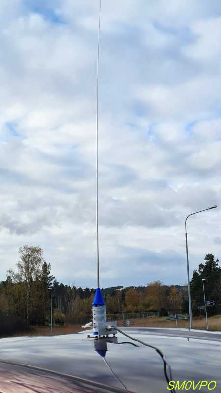
Full antenna on the roof of the car.
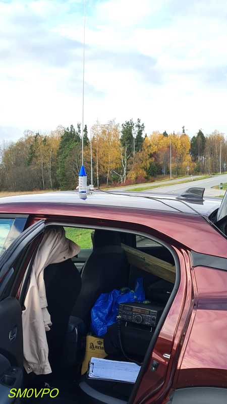
My FT-840 and logbook in the back seat of the car.
Had a nice 30 minute QSO with Bryan, and to be honest I was really impressed with the performance of this ridiculously simple antenna. VSWR was near perfect. I have had previous experience with insulated power cable coils getting warm, but I ran the full 100 Watts with no arcing, sparkalating or smoke. Stone-cold!!
Perhaps it was location, but this is one of the strongest QSO's I have had this year, and one of the few occasions I have heard VK stations. All on the smallest and simplest antenna
No more playing about with radials, the car chassis was more than adequate.
Best regards from Harry - SM0VPO
_________________
Everything in this world is either bacon, or it isn't bacon
They say that money cannot bring you happiness, but if you have it then you can always buy more bacon
admin- Admin
- Posts : 1144
Join date : 2012-11-24
Age : 72
Location : Märsta, Sweden -
Re: Yet another HF antenna project - miniature mobile telescopic
![]() by Andrew Fri Oct 22, 2021 12:56 pm
by Andrew Fri Oct 22, 2021 12:56 pm
Admin wrote:Hi Andrew,
I have known about capacitance "hats" for a few decades but I never bothered to try using them. I will do some experiments with the short antenna and see how they perform.
Q - Does a capacitance hat simply lower frequency? or does it actually add anything to the gain of the antenna? As I said I have no experience of using them.
Just for curiosity, I built a simple NEC model of a vertical dipole for the 10m band with an overall length of 5m, and ran a frequency sweep, next I modified the NEC model adding two 1m "hats" (50cm each spoke) at the top of bottom and reran the sweep, the results can be seen in this image (direct URL https://postimg.cc/w7HkBSQH )
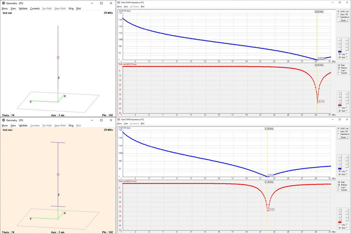
as you see, with the hats the resonance point moves from 29MHz to 21MHz so, in effect the capacitive hats lower the resonant frequency which in turn means that willing to bring the antenna back to 29MHz we'll be able to shorten it, notice that for simplicity I've set the feedpoint at the middle, but nothing forbids us from feeding the antenna from the bottom (note: impedance will raise to around 300 Ohm !) and this latter position is better since we won't need to run the coax at (almost) right angle (otherwise it would couple to the antenna and interfere with the pattern), by the way the hats may also be used for horizontal dipoles
Another effect of the use of capacitive hats is the fact that they lower the antenna Q so widening its bandwidth, it can be easily seen in this picture showing another NEC sweep in the 19 to 27 MHz range for the vertical dipole with "hats" (direct URL https://postimg.cc/NKVKVHNF )
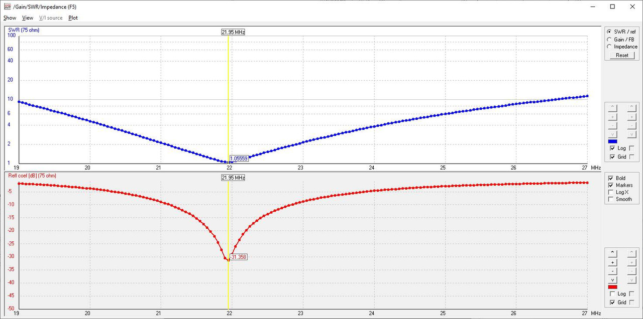
as you can see, the antenna has an SWR below 2:1 from 21 to 23 MHz, add to this the fact that using the hats, even if the antenna is low on ground (in the test I placed it at 1 meter), it has a low radiation angle and it's easy to see that hats may be useful, at times
[edit]
Oh and please, also see https://sites.google.com/site/lofturj/tf3lj_vertical for ideas and informations related to cap hats; if you check the project at that link I think it may be easy to see how, adding a tapped loading coil (to the capacitive hat design) may allow to obtain a decent match w/o the need for an external ATU
Andrew- Posts : 150
Join date : 2021-03-24
Age : 63
Location : Italy
admin likes this post
Re: Yet another HF antenna project - miniature mobile telescopic
![]() by Ivan Fri Oct 22, 2021 6:18 am
by Ivan Fri Oct 22, 2021 6:18 am
what about using a fishing rod (insulating) as a support for an inverted L made from stranded (litz) wire? The bottom of the rod would carry a loading coil, all attached to a magmount. Another magmount would keep the upper sloping wire. I attempted to draw it, looks terrible, sorry.
VBR from Ivan
Ivan- Posts : 793
Join date : 2012-11-25
Age : 64
Location : Praha, Czechia
Re: Yet another HF antenna project - miniature mobile telescopic
![]() by Andrew Thu Oct 21, 2021 5:21 pm
by Andrew Thu Oct 21, 2021 5:21 pm
https://www.kkn.net/dayton2004/Limited_Space_Antennas_W8JI_Dayton_2004.pdf
https://www.nonstopsystems.com/radio/antenna_80m_vertical-end-loaded.htm
https://www.buddipole.com/focahat.html
http://on5au.be/content/gp/cp-th.html
Andrew- Posts : 150
Join date : 2021-03-24
Age : 63
Location : Italy
admin likes this post
Re: Yet another HF antenna project - miniature mobile telescopic
![]() by Andrew Thu Oct 21, 2021 4:09 pm
by Andrew Thu Oct 21, 2021 4:09 pm
Admin wrote:Hi Andrew,
Thank you very much for all the comments. I think it is wonderful that there is so much knowledge on this forum and everyone is so willing to give the benefit of their experience.
Well, Harry, thank YOU for this place, it's what a forum should be, a place where people can exchange ideas and suggestions !
I have known about capacitance "hats" for a few decades but I never bothered to try using them. I will do some experiments with the short antenna and see how they perform.
Q - Does a capacitance hat simply lower frequency? or does it actually add anything to the gain of the antenna? As I said I have no experience of using them.
Let me start with some pointers
http://www.k0bg.com/caphats.html
http://www.antentop.org/w4rnl.001/mu8a.html
https://hamsignal.com/blog/don-t-forget-to-tie-the-capacitance-hat-elements-together
https://ham.stackexchange.com/questions/11918/capacitive-hats-on-wire-dipoles
which may hopefully be of help, then the effect of a capacitive "hat" (that's how most people calls them
As regards the loop on the ground, that will be tried for sure closer to Christmas when (stationary) mobile is no-longer possible. It is on my list, along with Ivan and my ideas for a variable length dipole.
My suggestion is to lay down the LoG (Loop on Ground) wire BEFORE it snows, the snow above the wire won't affect its performance and, even if you'll connect the feedline later on, once you'll have the wire in place, it will soon become invisible due to grass
Just have a look at this https://tapr.org/loop-on-ground-log-antenna/ and... yes, there's a LoG there ... under the snow
Thank you for all the ideas. Today I (while at work) I sorted out a few metres of high quality coax from the waste room and made up some cables to feed the new miniature antenna. I tested the miniature antenna on the car parked outside the house with 50m of cable leading in through the window to my rig. Now I have everything I need to work /p with the new antenna.
Thank you for the links. I will have a good look at those now. I am sure there are loads of other ideas that I can use to improve the design.
No need to thank, I think this is fun ! As for the coax... do you mean that you connected your home station to the antenna sitting on the car, parked near your home
Andrew- Posts : 150
Join date : 2021-03-24
Age : 63
Location : Italy
Re: Yet another HF antenna project - miniature mobile telescopic
![]() by admin Thu Oct 21, 2021 3:21 pm
by admin Thu Oct 21, 2021 3:21 pm
Thank you very much for all the comments. I think it is wonderful that there is so much knowledge on this forum and everyone is so willing to give the benefit of their experience.
I have known about capacitance "hats" for a few decades but I never bothered to try using them. I will do some experiments with the short antenna and see how they perform.
Q - Does a capacitance hat simply lower frequency? or does it actually add anything to the gain of the antenna? As I said I have no experience of using them.
As regards the loop on the ground, that will be tried for sure closer to Christmas when (stationary) mobile is no-longer possible. It is on my list, along with Ivan and my ideas for a variable length dipole.
Thank you for all the ideas. Today I (while at work
Thank you for the links. I will have a good look at those now. I am sure there are loads of other ideas that I can use to improve the design.
Very best regards from Harry - SM0VPO
_________________
Everything in this world is either bacon, or it isn't bacon
They say that money cannot bring you happiness, but if you have it then you can always buy more bacon
admin- Admin
- Posts : 1144
Join date : 2012-11-24
Age : 72
Location : Märsta, Sweden -
Re: Yet another HF antenna project - miniature mobile telescopic
![]() by Andrew Thu Oct 21, 2021 12:41 pm
by Andrew Thu Oct 21, 2021 12:41 pm
Admin wrote:Hi Andrew,
My 5m telescopic whip will go down to 3.5MHz and I have had some contacts down there. But on 14MHz and 18MHz I have had recent QSOs with Japan, using only 100 Watts. So I thought that the antenna was ok, even if there were days when there was virtually nothing to work. Maybe the off IK station.
Well, Harry, if propagation doesn't help there's little an antenna can do
As for the capacitive hats, I posted a wrong link, the image was this one
http://www.buzzbar.com/images/adphoto1.jpg
but the idea I was suggesting is to use telescopic whips like shown here
https://www.qsl.net/hb9mtn/hb9mtn_vertdip.html
but connecting the tips of the whips together with a piece of wire to form a ring, the resulting hat could be easily shortened and stored and by the way should be easily mounted at the top of the short "car whip" antenna, the effect would be lowering the resonant frequency of the antenna so possibly allowing to use a shorter coil and at the same time being able to use the antenna on a lower frequency (say the 40m band), by the way the same trick may be used for the longer antenna
I will look at getting the new 2m antenna down to 7MHz, but first I want to see how it performs over time with the 1.6m telescopic I have now. It may not be worth spending any money on a 2m telescopic (MFJ-1963), unless I can get one from Ebay?.
I rather think I will need a longer coil for 7MHz. According to my calculations for the 2m whip, I will need 28μH, which will need 50 turns on the existing former size, so it will have to be extended to 160mm instead of 100mm. Alternatively I could just use a 3.5m telescopic, but that will be heavier and be too long for bands above 20MHz.
Not sure you'll need to modify the coil, with a top capacitive hat you may be able to bring down the resonance enough to use the current coil, the idea may be worth a test I think
Perhaps I could build two antennas, one for the high bands and one for low bands?
For the moment I will be content with 14MHz, 18MHz, 21MHz and 24MHz, with the possibility of 29MHz should the conditions ever be ok.
Or it may be possible, with the help of a cap hat and a base loading coil to use the same antenna on lower bands too, then ok, it will still be short but since the hats mod is easy, also an advantage of the hats is that they allow to obtain low radiation angle even if the antenna is low on ground, which is a nice thing for DX contacts, just for curiosity I built a NEC model of such an antenna with the bottom at 1.5m from ground, a vertical whip of 2m and a simple capacitive hat and here's the resulting radiation pattern (direct link https://postimg.cc/yg7WGprT)
Thank you for your suggestions. All comments are great and ideas can always lead to something bigger. One suggestion I got on Twitter in a PM was to cut the bottom off a PET bottle and put that over the antenna coil when it rains or snows. Keep out all the weather.
You're welcome
Andrew- Posts : 150
Join date : 2021-03-24
Age : 63
Location : Italy
admin likes this post
Re: Yet another HF antenna project - miniature mobile telescopic
![]() by admin Wed Oct 20, 2021 11:15 pm
by admin Wed Oct 20, 2021 11:15 pm
My 5m telescopic whip will go down to 3.5MHz and I have had some contacts down there. But on 14MHz and 18MHz I have had recent QSOs with Japan, using only 100 Watts. So I thought that the antenna was ok, even if there were days when there was virtually nothing to work. Maybe the off IK station.
I will look at getting the new 2m antenna down to 7MHz, but first I want to see how it performs over time with the 1.6m telescopic I have now. It may not be worth spending any money on a 2m telescopic (MFJ-1963), unless I can get one from Ebay?.
I rather think I will need a longer coil for 7MHz. According to my calculations for the 2m whip, I will need 28μH, which will need 50 turns on the existing former size, so it will have to be extended to 160mm instead of 100mm. Alternatively I could just use a 3.5m telescopic, but that will be heavier and be too long for bands above 20MHz.
Perhaps I could build two antennas, one for the high bands and one for low bands?
For the moment I will be content with 14MHz, 18MHz, 21MHz and 24MHz, with the possibility of 29MHz should the conditions ever be ok.
Anyway, when this is tidied up and chucked in the back of the car then I will create a new project for the homepage. This will be perhaps the simplest, smallest and most versatile antenna I have made. The proof of the pudding is in the DX
Thank you for your suggestions. All comments are great and ideas can always lead to something bigger. One suggestion I got on Twitter in a PM was to cut the bottom off a PET bottle and put that over the antenna coil when it rains or snows. Keep out all the weather.
Very best regards from Harry - SM0VPO
_________________
Everything in this world is either bacon, or it isn't bacon
They say that money cannot bring you happiness, but if you have it then you can always buy more bacon
admin- Admin
- Posts : 1144
Join date : 2012-11-24
Age : 72
Location : Märsta, Sweden -
Re: Yet another HF antenna project - miniature mobile telescopic
![]() by Andrew Wed Oct 20, 2021 9:23 pm
by Andrew Wed Oct 20, 2021 9:23 pm
Andrew- Posts : 150
Join date : 2021-03-24
Age : 63
Location : Italy
admin likes this post
Re: Yet another HF antenna project - miniature mobile telescopic
![]() by admin Wed Oct 20, 2021 7:15 pm
by admin Wed Oct 20, 2021 7:15 pm
Funny enough, I did try a a capacity hat by clipping a couple of crocodile clips on the top, and the frequency changed quite a bit. 14.2MHz dropped to 13.3MHz with the small(ish) clips you woud use for a 5A bench PSU.
At this moment I am happy with it but I need to give it a serious trial. Naturally I will be parking my car "in the clear", on high ground, and miles away from any built-up areas where a computer SMPSU could be lurking
I still cannot get over how this little antenna performs, when compared with the 5m telescopic. I was expectiong to see almost an S-point reduction, but no. Nothing that is even measurable. An overgrown cotton-bobbin and a radio telescopic whip versus a 5m vertical with four ground-radials. I wonder if my GP antenna cable is defective? There is 15m of cable, but that should not explain so mand dB at 14MHz.
Thank you for the link. The picture there is not so good but at least it has the correct IP-address for Harry's Homebrew Homepages:

_________________
Everything in this world is either bacon, or it isn't bacon
They say that money cannot bring you happiness, but if you have it then you can always buy more bacon
admin- Admin
- Posts : 1144
Join date : 2012-11-24
Age : 72
Location : Märsta, Sweden -
Re: Yet another HF antenna project - miniature mobile telescopic
![]() by Andrew Wed Oct 20, 2021 2:17 pm
by Andrew Wed Oct 20, 2021 2:17 pm
Since the antenna is thought to be used with the car parked, did you consider the idea of adding a capacitive hat to the top of the stylus ? The hat support may be 3d printed (as long as it provides contacts) and could be small enough to be stored in the car, or the hat may even be a metal disc with a screw to lock it to the top of the stylus, that could allow using a smaller coil at base and/or covering lower frequencies
[edit]
the idea is having something like this
https://lh3.googleusercontent.com/proxy/eSXjpqSbgS9OGUhVuctukhjMnutUYrttwO7CrqmQQKxzlGp1Zobt8FDd792C0HXBxvHAQOf3k9wyjbRRDhJTb9tp
which could then be connected to the top of the stylus, notice that, for portability, the hat spokes may be telescopic and connected using a flexible wire
Andrew- Posts : 150
Join date : 2021-03-24
Age : 63
Location : Italy
admin likes this post
Yet another HF antenna project - miniature mobile telescopic
![]() by admin Wed Oct 20, 2021 12:32 pm
by admin Wed Oct 20, 2021 12:32 pm
Winter is on it's way and the temperature in Sweden is starting to fall. In another two months we can also expect snow and temperature below zero until about the end of February. Yesterday it was -3ºC. I have not been on the radio in my lunch breaks for a couple of weeks, because it has been so cold and deploying my wooden box, 5m telescopic and 4 or 5 radials is a bit of a pain. It is not really practical to do it with gloves on. Besides that, the 10kg wooden box occupies a significant space in the back of my little Nissan and it is difficult to have it there together with my wife's wheelchair. I can have one or the other, not both.
So I have been thinking a lot about an antenna that is easily deployed, without ground radials, and gives "reasonable" performance on the HF bands. Ideally it should be deployed in less than a minute. I am really interested in 14MHz, 18Mhz, 21MHz and 25MHz. 29MHz would also be nice if the conditions are good. I tried 10.1MHz a couple of times but my morse is a bit rusty. Also I had Swedish hams responding using the Swedish Morse alphabet, which made me loose the thread on more than one occasion, eg:
"--. .- -- -. .-.- .-. -... .--- ---. -." (Namn är Björn). Ok, I can live without 10MHz and the lower bands during daylight hours, although 7MHz would be nice.
Looking back at my logbook I see most signals are 54 to 59 with my 5m telescopic whip, so I thought I could loose perhaps 4dB or so. This means I can use a shorter antenna for mobile use. The loading coil design that I used mobile works good, so why not take a 2m long telescopic antenna, such as the MFJ-1963 ?
I have done some experiments with the short telescopic, but the longest I have available is only 1.6m. Ok, that will have to do, and if it works ok then I can order a 2m telescopic antenna. So out with the 3D printer, an SO-239 socket and a couple of neodymium magnets and try a prototype antenna, using the car are a ground-plane.
It works!!
I could not see much of a difference between this short HB mag-mount and my 5m ground-plane on the ground. Perhaps the radiation angle is lower with this miniature mag-mount on the roof of the car which makes up for the dB I am missing? Whatever, the results are really surprisingly good. This antenna could conceivably be used on a hand-held, battery rig HF rig, like the FT-817.
I used a 30-turn coil on a 40mm Diameter former and just soldered bits of wire at every turn so I can klank a crocodile clip on to select a tapping at 1-turn intervals. Coil length is 100mm. Tapped at 16 turns gives a perfect VSWR at 14.2MHz and the VSWR is less than 1.25:1 from 13.95MHz to 14.38MHz. 30 turns does (just) cover 10MHz, but I expect to get 7MHz when I have the full sized 2m telescopic antenna.
The completed coil is mounted on an aluminium chassis 8cm x 8cm. One extra edge is bent up to mount the SO-239 connector. I used small, weaker magnets, so that it will not stick to the car roof like a limpet - just enough to keep it firm and stable when there is a modest wind, but not good enough when driving.
This is the 3D printed loading coil. You can just see the small 8mm neodymium magnets - total 6, three either side.

This is the completed prototype antenna, placed on aluminium plates in the workshop (with a pair of pliers underneath to stick to the magnets).
Resonances on the car and on this 2m x 2m aluminium plate(s) are identical. The frequency just shifts about 20kHz LF when it is placed on the car, so the centre-frequency is 14.180MHz on the car at 16 turns.
Incidentally, the coil calculations were almost perfect as given in the Small HF antennas project on http://www.sm0vpo.com
With this little antenna I will be able to sit in my comfy car and not get my fingers frozen, and still work HF. There must be a catch, somewhere!! But I suppose you could say that success is not an acident, but it feels like it.
Very best regards from Harry - SM0VPO
PS - A little tip for posing pictures on this messageboard - post the pics on Twitter, then copy the Twitter picture link and insert it here
_________________
Everything in this world is either bacon, or it isn't bacon
They say that money cannot bring you happiness, but if you have it then you can always buy more bacon
admin- Admin
- Posts : 1144
Join date : 2012-11-24
Age : 72
Location : Märsta, Sweden -
Densil likes this post
Sponsored content
» 'Basic Antenna' Project
» My HF antenna in a small garden project continues
» The LoG antenna
» antenna 80m
|
|
|