Two Arduino Nano Based AM PWM TX
2 posters


Re: Two Arduino Nano Based AM PWM TX
![]() by dare4444 Tue Feb 01, 2022 9:13 pm
by dare4444 Tue Feb 01, 2022 9:13 pm
ADC sampling rate (~10kHz) and PWM frequency (37.5kHz) class D amplifier.
Here's how it sounds, a class D AF amp based on atmel. Sound is okay I would say. It means the Arduino with 10 bits and 64KHz pwm would sound a lot better.
https://youtu.be/O8of40tFsD8
Here's how it sounds, a class D AF amp based on atmel. Sound is okay I would say. It means the Arduino with 10 bits and 64KHz pwm would sound a lot better.
https://youtu.be/O8of40tFsD8
dare4444- Posts : 427
Join date : 2013-03-19
Re: Two Arduino Nano Based AM PWM TX
![]() by dare4444 Tue Feb 01, 2022 11:27 am
by dare4444 Tue Feb 01, 2022 11:27 am
This Arduino TX is using 10 bit ADC. Let's compare.
8 bit ADC's are horrid to use because of the 0.49% steps - I've seen enough of that. Arduino, being designed for hobby electronics, uses 4 times as many steps, so near to 0.1%, which is close to achievable signal to noise (plus hum) expected from common op-amp, transistor sensor circuits, or LM386 at 6V. Better than that would be wasted on hobbyist grade home-built electronics, and worse than that would be too steppy and horrid.
Whilst 16 bit ADC are commercially available, they take longer to settle, during which the hum or noise has moved, so you don't get a better measurement and it is slower. Therefore, 10 bit audio from our Arduino Nano is good enough (sound quality similar to that of a LM386 audio amplifier running at 6V).
dare4444- Posts : 427
Join date : 2013-03-19
Re: Two Arduino Nano Based AM PWM TX
![]() by dare4444 Tue Feb 01, 2022 10:48 am
by dare4444 Tue Feb 01, 2022 10:48 am
| 860 |
|
const byte ANTENNA = 9;
int duty;
int raw;
int bias = 192;
void setup(){
// set up Timer 0
TCCR0B &= B11111000;
TCCR0B |= B00000001;
// PWM Boost pins 5 & 6 to 64KHz
// set up Timer 1
TCCR1A = _BV (COM1A0); // toggle OC1A on Compare Match
TCCR1B = _BV(WGM12) | _BV(CS10); // CTC, no prescaler
OCR1A = 4; // compare A register value to 10 (zero relative)
// ADC Boost Start - sets ADC clock to 1MHz
// defines for setting and clearing register bits
#ifndef cbi
#define cbi(sfr, bit) (_SFR_BYTE(sfr) &= ~_BV(bit))
#endif
#ifndef sbi
#define sbi(sfr, bit) (_SFR_BYTE(sfr) |= _BV(bit))
#endif
// set ADC prescaler to 16
sbi(ADCSRA,ADPS2) ;
cbi(ADCSRA,ADPS1) ;
cbi(ADCSRA,ADPS0) ;
// ADC Boost End
}
void loop(){
{
raw = analogRead (0);
duty = bias + ((raw - 512)/4);
analogWrite(6, duty);
}
}
dare4444- Posts : 427
Join date : 2013-03-19
Re: Two Arduino Nano Based AM PWM TX
![]() by dare4444 Mon Jan 31, 2022 7:49 pm
by dare4444 Mon Jan 31, 2022 7:49 pm
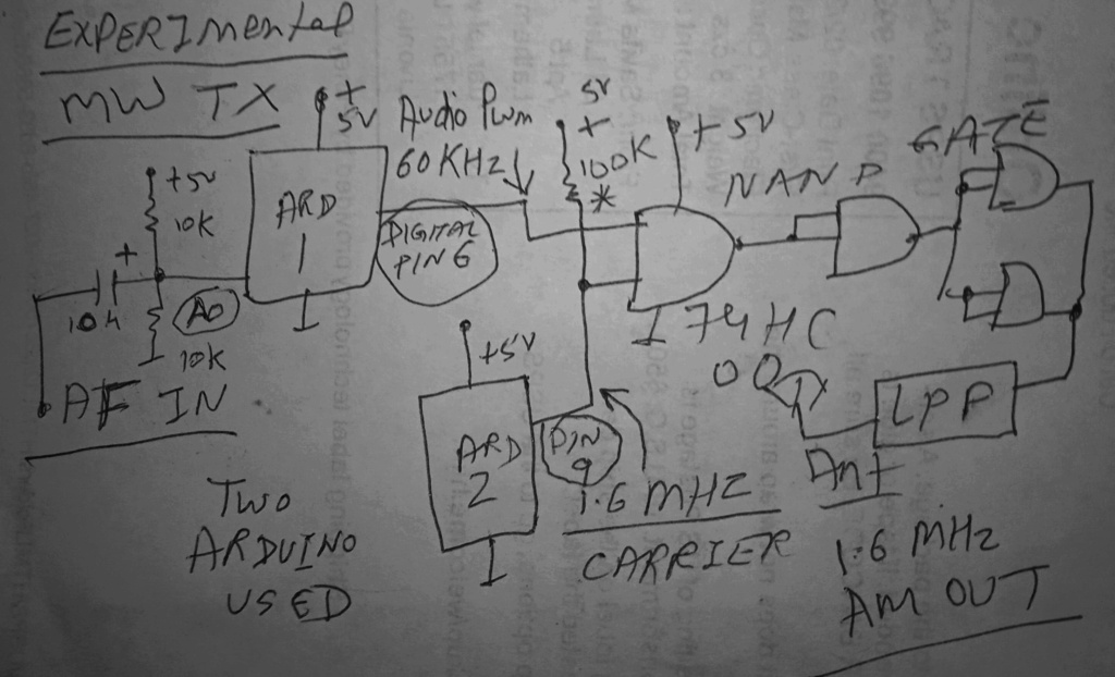
Ivan, Arduino has 3 timer counters. I want to shrink the project to only only Arduino generating the two signals for CD4011.
dare4444- Posts : 427
Join date : 2013-03-19
Re: Two Arduino Nano Based AM PWM TX
![]() by dare4444 Mon Jan 31, 2022 2:32 pm
by dare4444 Mon Jan 31, 2022 2:32 pm
Add a class D amplifier chain and it's super easy to get 10W of carrier. Transformer also gone. For the MOSFET drain matching use an air core .R1 x R2 x C1 x 0.455 = Frequency in Hz
R = Kilo ohm
C = nF
R2 = R2 + VR1
For VR1 use a 100K pot. R1 = 1M coil on PVC. Mosfet driver and PA required.
R = Kilo ohm
C = nF
R2 = R2 + VR1
For VR1 use a 100K pot. R1 = 1M
coil on PVC. Mosfet driver and PA required.
dare4444- Posts : 427
Join date : 2013-03-19
Re: Two Arduino Nano Based AM PWM TX
![]() by dare4444 Mon Jan 31, 2022 9:06 am
by dare4444 Mon Jan 31, 2022 9:06 am
Oh. Would it work satisfactorily at 1600KHz with just 5V supply? I checked datasheet, at 10V it's 1/120nS or 8MHz max. Good idea! Thank you so much for correcting my mistake. 5V is good for CD4011 at 1.6MHz I just checked its datasheet.Ivan wrote:A 4011 works with Vcc from 3 V up to 18 V. At lower Vcc it becomes a bit slower. If you feed it from 5 V, no level shifters are needed.
VBR Ivan
dare4444- Posts : 427
Join date : 2013-03-19
Re: Two Arduino Nano Based AM PWM TX
![]() by Ivan Mon Jan 31, 2022 6:16 am
by Ivan Mon Jan 31, 2022 6:16 am
A 4011 works with Vcc from 3 V up to 18 V. At lower Vcc it becomes a bit slower. If you feed it from 5 V, no level shifters are needed.
VBR Ivan
VBR Ivan
Ivan- Posts : 793
Join date : 2012-11-25
Age : 64
Location : Praha, Czechia
Re: Two Arduino Nano Based AM PWM TX
![]() by dare4444 Sun Jan 30, 2022 1:55 pm
by dare4444 Sun Jan 30, 2022 1:55 pm
| 852 |
|

dare4444- Posts : 427
Join date : 2013-03-19
Re: Two Arduino Nano Based AM PWM TX
![]() by dare4444 Sun Jan 30, 2022 12:29 pm
by dare4444 Sun Jan 30, 2022 12:29 pm
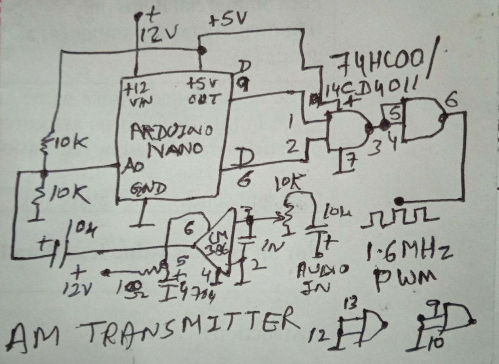
If we eliminate the 74HC00 then CD4011 can be used instead. CD4011 would work at 12V so a 5V to 12V level shifter with 2n7000 is needed to interface Arduino to nand gate mixer. Some extra parts but CD4011 is universally available even in local hobby shops or internet. CD4011 should work till 8MHz.

dare4444- Posts : 427
Join date : 2013-03-19
Re: Two Arduino Nano Based AM PWM TX
![]() by dare4444 Sat Jan 29, 2022 3:27 pm
by dare4444 Sat Jan 29, 2022 3:27 pm
Audio input needs to swing 4Vpp. Add LM386 amplifier at the input. Power the audio chip with 9 or 12V.
Power to 74HC00 chip comes from 5V output pin on the Arduino. It can source a maximum of 500ma when powered by 12V supply.
Power to 74HC00 chip comes from 5V output pin on the Arduino. It can source a maximum of 500ma when powered by 12V supply.
dare4444- Posts : 427
Join date : 2013-03-19
Re: Two Arduino Nano Based AM PWM TX
![]() by dare4444 Sat Jan 29, 2022 11:56 am
by dare4444 Sat Jan 29, 2022 11:56 am
x/* Arduino Nano Audio PWM Modulator. Open for improvement. Changes to the code welcome.
Experimental 1.6MHz AM transmitter using PWM.
Audio Input on Analog 0, PWM output on Digital 6.
I/O circuitry as follows:
Input: capacitor couple iPhone audio through 10uF.
Bias Input pin to 2.5V with one 10k resistor to 5v,
and another 10k resistor to ground to form a voltage divider.
*/
int duty;
int raw;
int bias = 192;
void setup(){
TCCR0B &= B11111000;
TCCR0B |= B00000001;
// PWM Boost pins 5 & 6 to 64KHz
// ADC Boost Start - sets ADC clock to 1MHz
// defines for setting and clearing register bits
#ifndef cbi
#define cbi(sfr, bit) (_SFR_BYTE(sfr) &= ~_BV(bit))
#endif
#ifndef sbi
#define sbi(sfr, bit) (_SFR_BYTE(sfr) |= _BV(bit))
#endif
// set ADC prescaler to 16
sbi(ADCSRA,ADPS2) ;
cbi(ADCSRA,ADPS1) ;
cbi(ADCSRA,ADPS0) ;
// ADC Boost End
}
void loop(){
raw = analogRead (0);
duty = bias + ((raw - 512)/2);
analogWrite(6, duty);
}
SKETCH for carrier generator Arduino
const byte ANTENNA = 9;
void setup()
{
// set up Timer 1
TCCR1A = _BV (COM1A0); // toggle OC1A on Compare Match
TCCR1B = _BV(WGM12) | _BV(CS10); // CTC, no prescaler
OCR1A = 4; // compare A register value to 10 (zero relative)
} // end of setup
void loop() {}
Theory: The 16 MHz clock is divided by 5 (that is, 3.2MHz) and that is used to toggle pin 9 at that rate, giving a frequency of 1600 KHz, since one toggle turns the output on, and second toggle turns it off.
If you hold the Arduino near an AM radio tuned to around 1600 KHz you should hear a silent carrier.
The OCR1A variable is related to the frequency. The OCR1A variable is one less than the actual divisor. OCR1A - Frequency 15 - 500 khz 14 - ~530 khz 13 - ~570 khz 12 - ~610 khz 11 - ~670 khz 10 - ~730 khz 9 - 800 khz 8 - ~890 khz 7 - 1000 khz 6 - ~1140 khz 5 - ~1330 khz 4 - 1600 khz 3 - 2000 khz 2 - ~2670 khz 1 - 4000 khz 0 - 8000 khz *would not recommend this setting
The formula is (16÷(OCR1A+1)÷2)×1000 = frequency in khz.
Regarding the PWM generator, the Arduino emulates such chips as the SG3525 or TL494 without the complicated wiring needed to actually use one of these chips, as most of the work is done natively on the Arduino. Sampling rate is 64KHz which is quite good for 5KHz audio bandwidth of medium wave broadcast band. Changes are welcome to the code for any improvement. 6ft wire antenna with proper matching is recommended. Add a 3ft ground radial. It should comfortably cover a 3BHk house.
The OCR1A variable is related to the frequency. The OCR1A variable is one less than the actual divisor. OCR1A - 4 - 1600 khz (16/5/2)
The formula is (16÷(OCR1A+1)÷2)×1000 = frequency in khz
--------
dare4444- Posts : 427
Join date : 2013-03-19
dare4444- Posts : 427
Join date : 2013-03-19
» PIC based DC/AC Mk-II (by Harry Lythall) suggestion
» Arduino etc. (was: GRID DIP OSCILLATOR)
» High Quality 16 bit AM PWM Arduino TX
» Proposed 1W PN2222A based FM AMP
» 100MHz IC based FM Transmitter
» Arduino etc. (was: GRID DIP OSCILLATOR)
» High Quality 16 bit AM PWM Arduino TX
» Proposed 1W PN2222A based FM AMP
» 100MHz IC based FM Transmitter
Permissions in this forum:
You can reply to topics in this forum|
|
|