High Quality 16 bit AM PWM Arduino TX
2 posters


Page 2 of 2 •  1, 2
1, 2
High Quality 16 bit AM PWM Arduino TX
![]() by dare4444 Wed Feb 02, 2022 9:25 am
by dare4444 Wed Feb 02, 2022 9:25 am
First topic message reminder :
In phase correct mode, the two outputs of Timer 1 are combined in 1:256 or 3.9K and 1M 1% precision resistors for 16 bit audio at 31.25KHz and fed to a nand gate switch. It switches the 1600KHz carrier on and off in accordance with the 31.25KHz AF PWM signal. The 31.25KHz AF is up-converted to 1600KHz RF. Sound quality is good and is suitable for transmitting music in part 15 environment around the house and yard. Sketch would be updated soon. Now we can have a high quality AM transmitter with two Arduino Nano boards and a couple of external components. CD players used 16 bit at 44KHz. This digital AM transmitter should sound excellent. Board 2 is programmable by modifying a single numerical digit for 800, 1000, and 1600 KHz output. It removes the hassle of finding crystals in this frequency range as they are uncommon now. Arduino Nano is cheap and just 4 bucks a piece.
FYI: D9 and D10 are giving out split ones and zeroes. 8bit + 8bit = resolution increases to 16bit.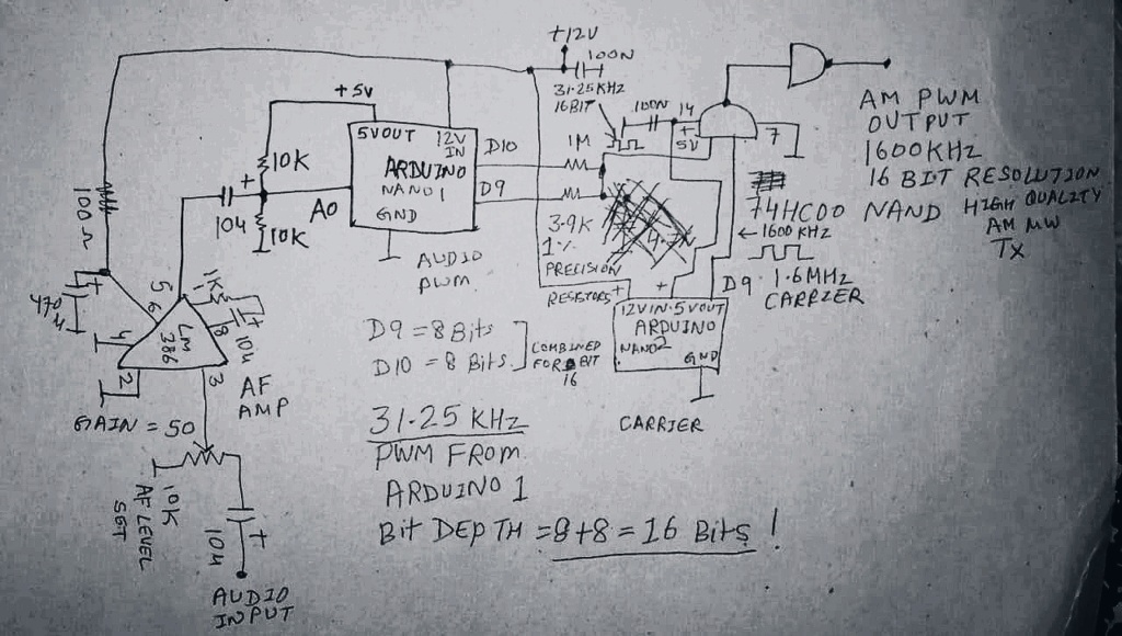
Last edited by dare4444 on Wed Feb 02, 2022 6:02 pm; edited 1 time in total
dare4444- Posts : 427
Join date : 2013-03-19
dare4444- Posts : 427
Join date : 2013-03-19
Re: High Quality 16 bit AM PWM Arduino TX
![]() by dare4444 Sat Feb 05, 2022 7:52 am
by dare4444 Sat Feb 05, 2022 7:52 am
It won't work. I just realized the increase in resolution is due to analogue weighing of the capacitor. My audio PWM is 31.25KHz , even if I choose C so that Fc is 60KHz it still won't work as the square waves are now turned into an analog.
These are characteristics of FM
FM has a signal to noise ratio of about 60dB. That can be managed by a bit depth of 10 bits.
FM has an audio bandwidth up to 15 kHz, so a sample rate of over 30 kHz is required - 32,768 Hz is a nice power of 2 that fits the bill.
So 10 bits per sample, 32,768 samples per second, 2 stereo channels - that’s a total bit rate of 655,360 bits per second (655 kbps).
Human ear dynamic range = 90dB when apartment has other noises like traffic, AC, etc.
Solution might be to take 2 digital pwm pulses and merge in xor gate using nand gates.
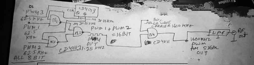
8 bit each. Arduino has 3 timers. 16 mhz /256 = 62.5 khz pwm from each timer. The timers are fed from a single audio source. We need 16 bit. So we combine the two pwm signal in two nand gates. The other pins of the nand gates are fed from a flip flop or divide by 2 . The third pwm signal is driving the flip flop so that the clock pulses remain synchronized. The output of two nand gates now merge into one nand gate. Its output is 62.5/2 = 31.25KHz 16 bit PWM audio signal. Even if 2 bits are lost to error it doesn't matter as 12-14 bit resolution is all we can hear (99%).
These are characteristics of FM
FM has a signal to noise ratio of about 60dB. That can be managed by a bit depth of 10 bits.
FM has an audio bandwidth up to 15 kHz, so a sample rate of over 30 kHz is required - 32,768 Hz is a nice power of 2 that fits the bill.
So 10 bits per sample, 32,768 samples per second, 2 stereo channels - that’s a total bit rate of 655,360 bits per second (655 kbps).
Human ear dynamic range = 90dB when apartment has other noises like traffic, AC, etc.
Solution might be to take 2 digital pwm pulses and merge in xor gate using nand gates.
8 bit each. Arduino has 3 timers. 16 mhz /256 = 62.5 khz pwm from each timer. The timers are fed from a single audio source. We need 16 bit. So we combine the two pwm signal in two nand gates. The other pins of the nand gates are fed from a flip flop or divide by 2 . The third pwm signal is driving the flip flop so that the clock pulses remain synchronized. The output of two nand gates now merge into one nand gate. Its output is 62.5/2 = 31.25KHz 16 bit PWM audio signal. Even if 2 bits are lost to error it doesn't matter as 12-14 bit resolution is all we can hear (99%).
dare4444- Posts : 427
Join date : 2013-03-19
Re: High Quality 16 bit AM PWM Arduino TX
![]() by dare4444 Sat Feb 05, 2022 1:04 am
by dare4444 Sat Feb 05, 2022 1:04 am
Harry, Ivan please check my question
dare4444- Posts : 427
Join date : 2013-03-19
Re: High Quality 16 bit AM PWM Arduino TX
![]() by dare4444 Fri Feb 04, 2022 8:40 pm
by dare4444 Fri Feb 04, 2022 8:40 pm
Ivan,
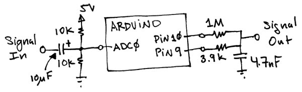
Question is, if we don't want an analogue output then removing the capacitor would give me digital 16 bit resolution PWM, am I right? I am trying to build an AM where the 16 bit digital signal is going to a 74hc00 on one input pin and other input pin is fed with 1600KHz carrier wave to generate 1600KHz PWM at 74HC00 output to drive a MOSFET in class D or a low pass filter feeding an antenna. I can remove the capacitor right for 16 bit digital pwm signal? Analogue has no use here.
My only doubt.
dare4444- Posts : 427
Join date : 2013-03-19
Re: High Quality 16 bit AM PWM Arduino TX
![]() by dare4444 Fri Feb 04, 2022 2:44 pm
by dare4444 Fri Feb 04, 2022 2:44 pm
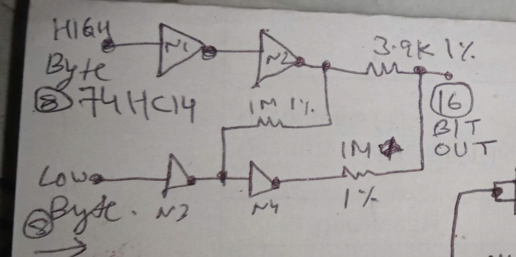
The inverters are needed to give some current
boost and also cancel out some errors which may be there.
The 1M between the top and below inverters is there to cancel some of them out.
dare4444- Posts : 427
Join date : 2013-03-19
Re: High Quality 16 bit AM PWM Arduino TX
![]() by dare4444 Fri Feb 04, 2022 12:37 pm
by dare4444 Fri Feb 04, 2022 12:37 pm
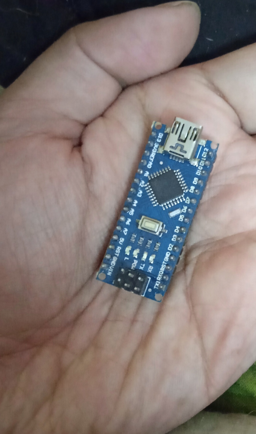
Arduino Nano. Other one eliminated. Two separate codes have been merged now on a single Nano. Touching D6 for carrier giving a light hiss on radio. Obviously the signal is very very weak and not travelling even a foot when I touch D6 with my multimeter probe. D9 and D10 are the 31.25KHz PWM pins.
Testing results will be posted soon.
dare4444- Posts : 427
Join date : 2013-03-19
Re: High Quality 16 bit AM PWM Arduino TX
![]() by dare4444 Thu Feb 03, 2022 10:23 pm
by dare4444 Thu Feb 03, 2022 10:23 pm
void setup() {
pinMode(5, OUTPUT);
pinMode(6,OUTPUT);
TCCR0A=0;//reset the register
TCCR0B=0;//reset tthe register
TCCR0A=0b01010011;// fast pwm mode
TCCR0B=0b00001001;// no prescaler and WGM02 is 1
OCR0A=0;//control value
}
When OCR0A=9 then output frequency would be 1600KHz at 50% square wave.
The code above has to be there after void setup.
It uses timer0 or pins 5 & 6. Timer1 is being used by the pwm modulator.
Putting it on Arduino 1 and taking carrier signal from D6, the other Arduino 2 could be eliminated. This code is outside the loop so it won't interfere with interrupts or other stuff
dare4444- Posts : 427
Join date : 2013-03-19
Re: High Quality 16 bit AM PWM Arduino TX
![]() by dare4444 Thu Feb 03, 2022 8:26 pm
by dare4444 Thu Feb 03, 2022 8:26 pm
Why is there a smiley face in place of number 8?
ICR1H = (PWM_FREQ >> ;
;
Where the smiley face is, the number '8' should be there followed by a ')' with no space between the two.
This completes the project. Have fun building it.
ICR1H = (PWM_FREQ >>
Where the smiley face is, the number '8' should be there followed by a ')' with no space between the two.
This completes the project. Have fun building it.
dare4444- Posts : 427
Join date : 2013-03-19
Re: High Quality 16 bit AM PWM Arduino TX
![]() by dare4444 Thu Feb 03, 2022 8:25 pm
by dare4444 Thu Feb 03, 2022 8:25 pm
Arduino Nano 1 sketch. The code is very simple for PWM generation. Arduino Nano 2 sketch remains the same I previously posted.
Arduino 1
// adc_to_pwm.pde
// ADC to PWM converter
// takes in audio data from the ADC and generates PWM at D9 and D10
// Timer1 PWM. 16 bit, Phase Correct, 31.25kHz - although ADC is 10 bit, in real time use & high sampling freq we get 8 bit only, output D9 & D10 are added together for 8 + 8 = 16 bit resolution. Sampling frequency is 38KHz (adc clk/ 13 cycles)
It would be hard to differentiate between CD player sound and this transmitter
#define PWM_FREQ 0x00FF // pwm frequency count - 255 or 11111111
#define PWM_MODE 0 // Fast (1) or Phase Correct (0)
#define PWM_QTY 2 // number of pwms are 2, each timer has 2 counters
void setup() {
// setup ADC Analog Input Pin A0
ADMUX = 0x60; // left adjust, selects A0 as adc input pin, internal vcc
ADCSRA = 0xe5; // turn on adc, sets prescaler to 16MHz clock / 32 = 500KHz ADC speed also known as free running mode, auto trigger
ADCSRB =0x07; // t1 capture for trigger
DIDR0 = 0x01; // turn off digital inputs for adc0 or pin A0
// setup PWM
TCCR1A = (((PWM_QTY - 1) << 5) | 0x80 | (PWM_MODE << 1)); //
TCCR1B = ((PWM_MODE << 3) | 0x11); // ck/1
TIMSK1 = 0x20; // interrupt on capture interrupt
ICR1H = (PWM_FREQ >> ;
;
ICR1L = (PWM_FREQ & 0xff); // & 0xff is hexadecimal numeric 16, adc clock freq is 500KHz, pwm frequency 500/16 - 31.25KHz
DDRB |= ((PWM_QTY << 1) | 0x02); // turn on outputs
sei(); // turn on interrupts - not really necessary with arduino
}
void loop() {
while(1); // gets rid of jitter for smooth pwm
}
ISR(TIMER1_CAPT_vect) {
// get ADC data
unsigned int temp1 = ADCL; // fetch low byte first
unsigned int temp2 = ADCH; // fetch high byte
// ADCH and ADCL 8 bits each are represented
// output high byte on OC1A
OCR1AH = temp2 >> 8; // takes top 8 bits
OCR1AL = temp2; // takes bottom 8 bits
// output low byte on OC1B
OCR1BH = temp1 >> 8;
OCR1BL = temp1;
// top 8 and bottom 8 bits are combined together in two precision resistors at pin D9 and D10 for 16 bit of audio resolution riding on a 31.25KHz PWM modulated square wave, sampling frequency is 38KHz, good enough for an AM transmitter!
}
Arduino 1
// adc_to_pwm.pde
// ADC to PWM converter
// takes in audio data from the ADC and generates PWM at D9 and D10
// Timer1 PWM. 16 bit, Phase Correct, 31.25kHz - although ADC is 10 bit, in real time use & high sampling freq we get 8 bit only, output D9 & D10 are added together for 8 + 8 = 16 bit resolution. Sampling frequency is 38KHz (adc clk/ 13 cycles)
It would be hard to differentiate between CD player sound and this transmitter
#define PWM_FREQ 0x00FF // pwm frequency count - 255 or 11111111
#define PWM_MODE 0 // Fast (1) or Phase Correct (0)
#define PWM_QTY 2 // number of pwms are 2, each timer has 2 counters
void setup() {
// setup ADC Analog Input Pin A0
ADMUX = 0x60; // left adjust, selects A0 as adc input pin, internal vcc
ADCSRA = 0xe5; // turn on adc, sets prescaler to 16MHz clock / 32 = 500KHz ADC speed also known as free running mode, auto trigger
ADCSRB =0x07; // t1 capture for trigger
DIDR0 = 0x01; // turn off digital inputs for adc0 or pin A0
// setup PWM
TCCR1A = (((PWM_QTY - 1) << 5) | 0x80 | (PWM_MODE << 1)); //
TCCR1B = ((PWM_MODE << 3) | 0x11); // ck/1
TIMSK1 = 0x20; // interrupt on capture interrupt
ICR1H = (PWM_FREQ >>
ICR1L = (PWM_FREQ & 0xff); // & 0xff is hexadecimal numeric 16, adc clock freq is 500KHz, pwm frequency 500/16 - 31.25KHz
DDRB |= ((PWM_QTY << 1) | 0x02); // turn on outputs
sei(); // turn on interrupts - not really necessary with arduino
}
void loop() {
while(1); // gets rid of jitter for smooth pwm
}
ISR(TIMER1_CAPT_vect) {
// get ADC data
unsigned int temp1 = ADCL; // fetch low byte first
unsigned int temp2 = ADCH; // fetch high byte
// ADCH and ADCL 8 bits each are represented
// output high byte on OC1A
OCR1AH = temp2 >> 8; // takes top 8 bits
OCR1AL = temp2; // takes bottom 8 bits
// output low byte on OC1B
OCR1BH = temp1 >> 8;
OCR1BL = temp1;
// top 8 and bottom 8 bits are combined together in two precision resistors at pin D9 and D10 for 16 bit of audio resolution riding on a 31.25KHz PWM modulated square wave, sampling frequency is 38KHz, good enough for an AM transmitter!
}
dare4444- Posts : 427
Join date : 2013-03-19
Re: High Quality 16 bit AM PWM Arduino TX
![]() by dare4444 Thu Feb 03, 2022 8:15 am
by dare4444 Thu Feb 03, 2022 8:15 am
Ivan wrote:I disagree. My experience is that parts from the same production lot are often "shifted" the same way. In a pack of 100K +-5% resistors there are e.g. several 101K, 103K etc., but no 99K. A precise ohmmeter is the only sure solution.dare4444 wrote:... all those "too low" and "too high" values compensate each other and it becomes, suddenly, a big chain with a much better accuracy, through the law of large numbers...
VBR Ivan
Oh. Thanks for the knowledge Ivan. I forgot to mention 1% precision resistors.
dare4444- Posts : 427
Join date : 2013-03-19
Re: High Quality 16 bit AM PWM Arduino TX
![]() by Ivan Thu Feb 03, 2022 6:05 am
by Ivan Thu Feb 03, 2022 6:05 am
I disagree. My experience is that parts from the same production lot are often "shifted" the same way. In a pack of 100K +-5% resistors there are e.g. several 101K, 103K etc., but no 99K. A precise ohmmeter is the only sure solution.dare4444 wrote:... all those "too low" and "too high" values compensate each other and it becomes, suddenly, a big chain with a much better accuracy, through the law of large numbers...
VBR Ivan
Ivan- Posts : 793
Join date : 2012-11-25
Age : 64
Location : Praha, Czechia
Re: High Quality 16 bit AM PWM Arduino TX
![]() by dare4444 Wed Feb 02, 2022 11:51 pm
by dare4444 Wed Feb 02, 2022 11:51 pm
If you have 10 resistors of 200 Ohms at 5% in series, it's reasonably likely that one will be 201 Ohm, another 199 Ohm, another will be 204 Ohm, yet another will be 191 Ohm, etc etc, and all those "too low" and "too high" values compensate each other and it becomes, suddenly, a big 2k chain with a much better accuracy, through the law of large numbers.
This is only in the specific case of the same value resistors in series. While different values in series are also likely to become more accurate on average.
Full 16bit CD quality sound is possible from Arduino if the two resistors have a precision reaching 0.3% instead of 1%.
Several metal film resistors in series of the same value would do the trick. 100K of 1% metal film x 10 = 1M
dare4444- Posts : 427
Join date : 2013-03-19
Re: High Quality 16 bit AM PWM Arduino TX
![]() by dare4444 Wed Feb 02, 2022 2:38 pm
by dare4444 Wed Feb 02, 2022 2:38 pm
Use two PWMs, and use one pin for high bytes and another for low bytes.
Using two PWM pins and adding them together means it’s possible to add extra bits of resolution. This requires using different values of resistors on each pin. For example, using the same value of resistors on two PWM pins increases the resolution by one bit. Two pins with a resistor value ratio of 1:4 increases the resolution by four bits, and so on.
This is how it works.
dare4444- Posts : 427
Join date : 2013-03-19
High Quality 16 bit AM PWM Arduino TX
![]() by dare4444 Wed Feb 02, 2022 9:25 am
by dare4444 Wed Feb 02, 2022 9:25 am
In phase correct mode, the two outputs of Timer 1 are combined in 1:256 or 3.9K and 1M 1% precision resistors for 16 bit audio at 31.25KHz and fed to a nand gate switch. It switches the 1600KHz carrier on and off in accordance with the 31.25KHz AF PWM signal. The 31.25KHz AF is up-converted to 1600KHz RF. Sound quality is good and is suitable for transmitting music in part 15 environment around the house and yard. Sketch would be updated soon. Now we can have a high quality AM transmitter with two Arduino Nano boards and a couple of external components. CD players used 16 bit at 44KHz. This digital AM transmitter should sound excellent. Board 2 is programmable by modifying a single numerical digit for 800, 1000, and 1600 KHz output. It removes the hassle of finding crystals in this frequency range as they are uncommon now. Arduino Nano is cheap and just 4 bucks a piece.
FYI: D9 and D10 are giving out split ones and zeroes. 8bit + 8bit = resolution increases to 16bit.
FYI: D9 and D10 are giving out split ones and zeroes. 8bit + 8bit = resolution increases to 16bit.
Last edited by dare4444 on Wed Feb 02, 2022 6:02 pm; edited 1 time in total
dare4444- Posts : 427
Join date : 2013-03-19
Page 2 of 2 • 1, 2
» INFO (not question) High Quality from street market
» Two Arduino Nano Based AM PWM TX
» Arduino etc. (was: GRID DIP OSCILLATOR)
» Fm tx audio quality
» New project on sm0vpo.com - Arduino based Radio Control Transmitter Coder
» Two Arduino Nano Based AM PWM TX
» Arduino etc. (was: GRID DIP OSCILLATOR)
» Fm tx audio quality
» New project on sm0vpo.com - Arduino based Radio Control Transmitter Coder
Permissions in this forum:
You can reply to topics in this forum|
|
|