10mW 4 Channel PLL FM Transmitter


Re: 10mW 4 Channel PLL FM Transmitter
![]() by dare4444 Fri Mar 18, 2022 7:28 pm
by dare4444 Fri Mar 18, 2022 7:28 pm
dare4444- Posts : 427
Join date : 2013-03-19
Re: 10mW 4 Channel PLL FM Transmitter
![]() by Ivan Thu Mar 17, 2022 2:16 pm
by Ivan Thu Mar 17, 2022 2:16 pm
Hi all,Admin wrote:A few years ago manufacturers stopped providing those silicon heat-sink pads, and the plastic insulators so you could bolt a transistor to a heatsink.
if a transistor can be bolted to a heatsink directly using a bit of thermoconductive grease only, the thermal resistance is the smallest. If not, a PTFE (teflon) tape is quite good. It can be bought e.g. as a sealing tape for plumbers.
I would not recommend gluing. First, certain types of glue are good thermal insulators when hardened, and gluing makes changing the transistor hard if the transistor puffs out its compressed smoke.
VBR from Ivan
Ivan- Posts : 794
Join date : 2012-11-25
Age : 64
Location : Praha, Czechia
Re: 10mW 4 Channel PLL FM Transmitter
![]() by dare4444 Wed Mar 16, 2022 5:15 pm
by dare4444 Wed Mar 16, 2022 5:15 pm
Saving your text in notepad. They are good for reference later and it's definitely ok for me. Do as per your plan. Some of the most important ckts like 2222 and bs170 amp I've not yet put on your webpages.
dare4444- Posts : 427
Join date : 2013-03-19
Re: 10mW 4 Channel PLL FM Transmitter
![]() by admin Wed Mar 16, 2022 12:34 pm
by admin Wed Mar 16, 2022 12:34 pm
dare4444 wrote:I removed most of my ckts. Again met someone who asked me for schematics and he's big time kit seller. Everyone is just making money as the hobby spirit is gone. BS170 4W amp I sent had him. If LtSpice was so accurate in case of PN2222A amp where simulation Vpeak was just a few hundred millivolts higher than the prototype, the BS170 amp should work as Spice showing 4.5W Out with 5.5W DC Input. Assume 450mW max heat dissipation per mosfet, would glueing to copper clad board work as heatsink? I think so. 450mW dissipation it can handle.
Hi Joy,
Interesting points.
I few years ago manufacturers stopped providing those silicon heat-sink pads, and the plastic insulators so you could bolt a transistor to a heatsink.
My solution was to put some photocopy paper in the fryingpan with a little rape-seed oil, about 150°C for a few minutes, then cut it to make my own insulators. I have also tried with wax with equal success.
Glue? I never thought about that. If you do not need to insulate the device, then why not use glue? I did an article on heatsink size calculations and I have a calculator on the homepages for it.
Today, I skip the insulators and make heatsinks that are like U-wings with the device sitting in the bottom of the U. I bolt the device to an insulated bit of the board, but put a bit of aluminium under the device, then bend the sides up to make the U. I sometimes use several U's in a sandwich so that I get several wings / fins, as long as the surface area is sufficient to dissipate the heat.
I also found that a black spirit felt-tipped pen (no thickness for the ink to insulate) will increase the heat radiation and will dissipate more heat than untreated aluminium or copper.
BTW, you may be interested in my latest projects. I have four different projects that are built, tested and almost ready to publish. They are all "spin-offs" from my transverter project:
1 - Rule-of-Thumb for calculating ferrite rings for RF - with worked examples. Ivan asked me to clarify this in the transverter project, but I ended up up putting it into a new article
2 - "What is the range of this transmitter?" - so I have an article with graphs and worked examples
3 - 200mW FM transmitter - now working in my home, and gives a very good quality from am MP3 player - this is the oscillator section of my transverter
4 - The transverter. Working but the "final prototype" has mixer problems that I need to solve before I publish
1, 2 and 3 are just about ready. 4 I am working on. When I wrote these articles I was thinking about you and the work you are doing with VHF FM since the information could be useful to you. For example, impedance matching is easy using ferrite rings, but at VHF? Yes, why not, they seem to work really well at 140MHz and at 100MHz they make design more simple, and they are broadband. In addition, the magnetic path in the ring is closed so there is almost no coupling between coils to cause self-oscillation with a higher gain amplifier.
Anyway, I will ask Ivan if he can review the three working articles before I publish. He always seems to find basic things that I forgot, or should explain better.
Before I can publish I have to review my homepages because the storage space is just about full. I have several illustrations that have 500kB or more that can be reduced dramatically to make room for more projects. I moved my home server from the RaPI to a desktop "boat-anchor" computer. No shortage of space there, it is just the altervista.org site that has "space-full" errors. On the home server I am getting an average of about 3136.986 visitors a day (250,000 this year), and since January there has been over 21GB of data downloaded.
I have a suggestion for you: since there are no size restriction on my home server, I would like to move your projects to a section of the home server dedicated to just your projects, with a link from www.sm0vpo.com and sm0vpo.altervista.com. Is this ok with you? That would give me a lot more space on altervista.
PS - When you produce your project circuits there are several things you can do. In PhotoShop you can add a watermark. Also, in the JPG files there are a number of bytes used in the header to define the file type. Some of those bytes are vacant, and you can use HEXEDIT to put in a couple of words of your own. I believe that id a picture is re-sized then saving will retain the data, as well as the watermark.
Very best regards from Harry - SM0VPO
_________________
Everything in this world is either bacon, or it isn't bacon
They say that money cannot bring you happiness, but if you have it then you can always buy more bacon

admin- Admin
- Posts : 1144
Join date : 2012-11-24
Age : 72
Location : Märsta, Sweden -

Re: 10mW 4 Channel PLL FM Transmitter
![]() by dare4444 Sun Mar 13, 2022 12:10 pm
by dare4444 Sun Mar 13, 2022 12:10 pm
dare4444- Posts : 427
Join date : 2013-03-19
admin likes this post
Re: 10mW 4 Channel PLL FM Transmitter
![]() by dare4444 Sat Mar 12, 2022 8:31 pm
by dare4444 Sat Mar 12, 2022 8:31 pm
Ivan wrote:Hi Joy,dare4444 wrote:Get 26 of them DIP packaging for less than six bucks.
I am thinking of buying a few hundreds of them
please be more specific. What did you buy to make you happy?

This guy ran out of the pub and shouted:"I have it! I have it!" I asked him politely what does he have. He hit me into my face and said:"Now, you have it, too."
Keep fun!
VBR from Ivan
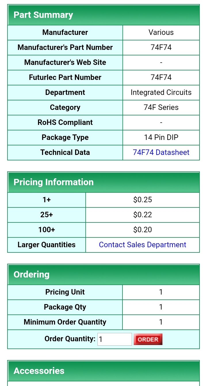
Sorry Ivan, I had missed your reply and just noticed this. I'm talking about 74F74 as 160MHz prescalers. It's a steal here:
https://www.futurlec.com/74F/74F74pr.shtml
They are genuine. I've ordered from them since 2009. All genuine parts. Free shipping > $50. 74F74 X 300 ICs = $60 free shipping. I use them in my PLL circuits. They are an excellent alternative to obsolete prescaler chips. They work on 2m band too.
dare4444- Posts : 427
Join date : 2013-03-19
Re: 10mW 4 Channel PLL FM Transmitter
![]() by dare4444 Sat Mar 12, 2022 8:18 pm
by dare4444 Sat Mar 12, 2022 8:18 pm
Last edited by dare4444 on Sat Jun 18, 2022 9:06 pm; edited 2 times in total
dare4444- Posts : 427
Join date : 2013-03-19
Re: 10mW 4 Channel PLL FM Transmitter
![]() by dare4444 Sat Mar 12, 2022 12:38 am
by dare4444 Sat Mar 12, 2022 12:38 am
Last edited by dare4444 on Sat Jun 18, 2022 9:01 pm; edited 2 times in total
dare4444- Posts : 427
Join date : 2013-03-19
Re: 10mW 4 Channel PLL FM Transmitter
![]() by John_1981 Sat Mar 12, 2022 12:04 am
by John_1981 Sat Mar 12, 2022 12:04 am
On the subject of PLL frequency synthesizers, I was hampered by the lack of availability of chips such as the 74HC4049 so I got hold of some MC145157 serial load chips from a supplier in China for next to nothing. I expected them to be fakes but they worked for me. Have you thought of trying something like this? I like being able to dial in the frequency using DIL switches etc. but now find it more convenient with a 3 wire serial interface and PIC/Arduino for control. The MC145157 gives me N and R values of anything between 3 and 16,383 so you can use just about any crystal you have in your junk box for the reference frequency.
If you used a ceramic resonator as the reference you could probably frequency modulate this directly and with suitable N and R values you would get your +/-75kHz deviation at the final frequency
John_1981- Posts : 32
Join date : 2021-11-07
Re: 10mW 4 Channel PLL FM Transmitter
![]() by dare4444 Tue Mar 08, 2022 2:09 pm
by dare4444 Tue Mar 08, 2022 2:09 pm
The board lay open on a wooden table all day. Directly overhead was a ceiling fan and when I turned it in at max speed the large air flow caused frequency to increase by 6.5KHz . Turning off returned it to 1KHz of where it was before.
The board lay open 24 hours and drift was less than 5KHz.
Few things I didn't understand. When oscillator output resistor was 1K the frequency was stiffer and increasing it to 2.2K loosened it up a bit. Counterintuitive? Did 1K matched Impedances better? The AF quality suffered so 2.2K removed the audio distortion.
In Harry's 150mW FM TX the buffer takes DC biasing directly from oscillator emitter yet he states mega stable. In my experience it must drift.
T3 in mine was DC biased by T2 and it introduced drift. Separating the bias cancelled it out. I noticed drift when I built it Harrys' style or this 5mW two transistor TX.
The drift figure I stated for my 300mW TX is as good as it gets or what? Spice simulation S12 = -57dB from 2.2K input of T2 to PN2222A's output of 50ohm. How's this figure for reverse isolation? Let's say it's -50dB.
I took much pain for frequency stability when a simple PLL would work better, lol but I was overly curious about LC oscillators and all the factors involved in frequency drift.
dare4444- Posts : 427
Join date : 2013-03-19
Re: 10mW 4 Channel PLL FM Transmitter
![]() by dare4444 Mon Mar 07, 2022 12:01 pm
by dare4444 Mon Mar 07, 2022 12:01 pm
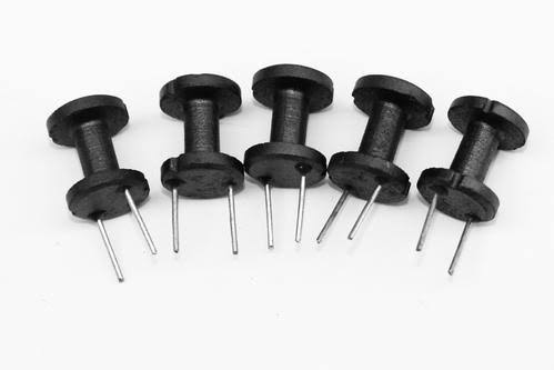
#43 material was limited to 450mW at 100MHz.
Even the drum cores used in RFI chokes are grey ferrite and cost 10 cents. Are they really all that bad when compare to 43 material? I'm not sure how much losses are we gonna see at 100MHz.
These are 1 cents each in India when ordering in bulk. A FM transmitter based on single BS170 oscillator and two BS170 buffer stages would be a nice addition to your home pages. Something new just like the 7812 as RF amplifier you uploaded a few years ago.
dare4444- Posts : 427
Join date : 2013-03-19
Re: 10mW 4 Channel PLL FM Transmitter
![]() by admin Sun Mar 06, 2022 3:09 pm
by admin Sun Mar 06, 2022 3:09 pm
dare4444 wrote:Hello again,
Harry those drum ferrite cores are sold everywhere and dirt cheap. They are used widely in smps and power supplies. Do they work up to 100MHz?
The 43 material bn-43-2402 and bn-43-202 binocular worked fine at 103Mhz and used only in driver stages.
Is the grey ferrite material used in drum cores vastly different from #43 ?
4W power needed very fine tuning. It was the limit of 3553 with no LPF. Considering 10dB gain the bn43-202 is delivering approximately 350mW.
+ - 1KHz frequency drift in 2011. No Varactor = less drift. Osc C is NP0 in parallel with 2cm gimmick for fine tuning. Gimmick is more stable than a cheap trimmer.
BF199 x 5 low gain buffer stages between Osc and driver achieved frequency and RF stability and removed coils and/or trimmers between stages. Only the final L network needs tweaking. Good project for novices, right? Internet has got so many FM TX ckts but they are all conventional and follow more or less the same design with L and B between stage.
My circuit is a no brainer, but still it is a bit different and unique. This uniqueness is what drives us to design our own ckts. The Z base of BF199 x 3 before the driver is 300ohm and its preceding BF199 sees around 1000 ohm at its collector if we add 2pF stray in primary 4T.
Isn't it simpler, no critical tuning anywhere except the L match. I gave this ckt to the guy who sells kits. His own design even after trying to copy my 2222 amp didn't work. I'm not sure why people don't want to learn instead of ripping other people off. It's really bothering me, lol.
BF199 or S9018 used. The oscillator is so much isolated that its drift was + - 1KHz!!
Hi Joy,
I hope to post a circuit sometime during the week that may interest you. It is a 2-transistor (and one diode) FM transmitter.
There is only one control - frequency. Frequency range is from 90MHz to 130MHz (one trimming pot plus a variable resistor for fine-tune).
I used a ferrite core for the output stage, which matches directly to 50Ω from the collector of the linear PA. Output power is 180mW (measured) +22dBm. Runs from 12V.
Frequency stability is ok, but if the tuned circuit and tuning bits are physically several mm from the transistor then it is good. Frequency stability is best at 90MHz to 110MHz.
There is capacitive decoupling to reduce the gain, but that was 22pf at 130MHz. You could make it 33pf if you use 90-110MHz range. The feedback controls the gain so the output level is repeatable.
The project is a part of my synthesised transverter, but it is just the oscillator section. You will need a LP filter at the output, but I have not shown that.
The board I have for the transverter also includes a synthesiser so that it could be used to form a synthesised transmitter. To do that would need a very low frequency crystal so that the divide rate is high, otherwise the PLL would negate the modulation.
For the "kitsrus" project I used a lower divide rate, but a long time-constant in the loop filter. It had the effect of giving a "frequency-lock" even though it could not achieve a phase-lock, due to modulation. The CD4046 PSD has a "high-tristate-low" function so it can be used in this way.
Ok, I will continue. I want to get some quality time on the bench today, as in a couple of weeks the ground frost will be gone and my duties will include gardening; cleaning, digging, pruning, painting, cutting, etc. That always takes priority over fun, hobby things
Have a nice day - Harry - SM0VPO
_________________
Everything in this world is either bacon, or it isn't bacon
They say that money cannot bring you happiness, but if you have it then you can always buy more bacon
admin- Admin
- Posts : 1144
Join date : 2012-11-24
Age : 72
Location : Märsta, Sweden -
Re: 10mW 4 Channel PLL FM Transmitter
![]() by Ivan Sun Mar 06, 2022 7:44 am
by Ivan Sun Mar 06, 2022 7:44 am
Hi Joy,dare4444 wrote:Get 26 of them DIP packaging for less than six bucks.
I am thinking of buying a few hundreds of them
please be more specific. What did you buy to make you happy?
This guy ran out of the pub and shouted:"I have it! I have it!" I asked him politely what does he have. He hit me into my face and said:"Now, you have it, too."
Keep fun!
VBR from Ivan
Ivan- Posts : 794
Join date : 2012-11-25
Age : 64
Location : Praha, Czechia
Re: 10mW 4 Channel PLL FM Transmitter
![]() by dare4444 Sat Mar 05, 2022 7:50 pm
by dare4444 Sat Mar 05, 2022 7:50 pm
for less than six bucks.
I am thinking of buying a few hundreds of them, Haha. 100 would cost me $22 + shipping when order is less than < $50. In Western countries it's getting harder to buy DIP 16 packaging. Futurlec sells genuine parts. I first ordered from them in 2008.
I even got a few 74HC4059 they work easily at 25MHz. PLL was then a very simple circuit. It's no longer available.
Even RF transistors like 2n3553 are no longer produced. Why's that? New transistors come, they stay in the market for a few years and then disappear. BFG135 was one such transistor. Now the focus is shifting to UHF like 850MHz and higher.
22 cents is a steal. I use them for prescaler upto 160MHz, the 74F74 .
$0.22 is x10 cheaper than a 64/256 prescaler chip.
dare4444- Posts : 427
Join date : 2013-03-19
Re: 10mW 4 Channel PLL FM Transmitter
![]() by dare4444 Fri Mar 04, 2022 5:57 pm
by dare4444 Fri Mar 04, 2022 5:57 pm

Yes Ivan, both are important.
VEB is 4V for 3553. Why this guy didn't use a simple
matching network?
dare4444- Posts : 427
Join date : 2013-03-19
Re: 10mW 4 Channel PLL FM Transmitter
![]() by Ivan Fri Mar 04, 2022 5:00 pm
by Ivan Fri Mar 04, 2022 5:00 pm
There are ways to transform voltage and current - using an (auto)transformer or a stub of RF line.dare4444 wrote:
Yes, I know there's no possible way to transform voltage and current
Driving the base directly with high voltage swing kills the transistor. I'm not sure how this 3.5W TX managed to stay on air.
Two things must be observed when driving a transistor with common emitter:
1. The negative half-wave (for NPN) may not exceed the maximum reverse base-emitter voltage, othervise an avalanche breakthrough may take place. If a thermal breakthrough follows, the poor transistor dies.
2. The current during the positive half-wave (for NPN) must be limited not to exceed the maximum forward base current.
VBR Ivan
Ivan- Posts : 794
Join date : 2012-11-25
Age : 64
Location : Praha, Czechia
Re: 10mW 4 Channel PLL FM Transmitter
![]() by dare4444 Fri Mar 04, 2022 11:35 am
by dare4444 Fri Mar 04, 2022 11:35 am
Ivan wrote:Hi Joy,dare4444 wrote:Does this kind of topology work? If it works is it due to the tuned ckt at collector of 2n3866? Tuned LC = large voltage swing at 2n3866 collector which is transformed to a lower voltage and higher current with the 27pF collector coupling capacitor directly feeding the base of 2n3553 final. Am I right?
I see nothing special in the topology at the first glance.
Yes, a parralel tuned circuit increases the voltage swing Q times.
No, a capacitive coupling does not transform voltage / current, but it can match the impedances.
The final stage seems to work in the C class, which is possible for FM. The filtration of higher harmonics seems to be rather insufficient at the output.
VBR from Ivan
Yes, I know there's no possible way to transform voltage and current but some engineer told me that it does, haha so I inserted it in the question.
I killed a lot of genuine 2n5109 back in 2005 when I drove them with driver collector to final amp base with capacitor coupling and no inductor. Back then all transistors were genuine on eBay. I think I destroyed 50 of them. Ebay was taking off during that time and thugs in China decided to manufacturer their own fake 3866/5109 with the die of a BD139. This transistor got Ft of 190MHz . Explains 4dB power gain I got, shiny metal cans. Manufacturing cost is a few cents and they sell for $1.3
Driving the base directly with high voltage swing kills the transistor. I'm not sure how this 3.5W TX managed to stay on air.
dare4444- Posts : 427
Join date : 2013-03-19
Re: 10mW 4 Channel PLL FM Transmitter
![]() by Ivan Fri Mar 04, 2022 7:16 am
by Ivan Fri Mar 04, 2022 7:16 am
Hi Joy,dare4444 wrote:Does this kind of topology work? If it works is it due to the tuned ckt at collector of 2n3866? Tuned LC = large voltage swing at 2n3866 collector which is transformed to a lower voltage and higher current with the 27pF collector coupling capacitor directly feeding the base of 2n3553 final. Am I right?
I see nothing special in the topology at the first glance.
Yes, a parralel tuned circuit increases the voltage swing Q times.
No, a capacitive coupling does not transform voltage / current, but it can match the impedances.
The final stage seems to work in the C class, which is possible for FM. The filtration of higher harmonics seems to be rather insufficient at the output.
VBR from Ivan
Ivan- Posts : 794
Join date : 2012-11-25
Age : 64
Location : Praha, Czechia
Re: 10mW 4 Channel PLL FM Transmitter
![]() by dare4444 Thu Mar 03, 2022 11:25 pm
by dare4444 Thu Mar 03, 2022 11:25 pm
I never tried it. So many L and C. My circuit got extra parts but its easy, and this got fewer parts but needs tuning of trimmers. My 4W TX has less drift and grey binocular cores mean broadband operation.
In your opinion which would you prefer for ease?
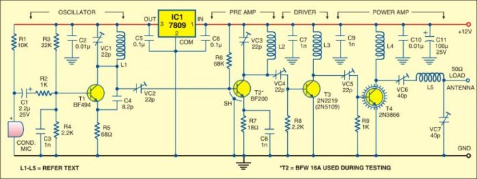
I've a doubt. 2n3866 driver is biased for 5-10ma here, collector has a tuned circuit and directly feeds 2n3553's base via a 27pF cap.
Does this kind of topology work? If it works is it due to the tuned ckt at collector of 2n3866? Tuned LC = large voltage swing at 2n3866 collector which is transformed to a lower voltage and higher current with the 27pF collector coupling capacitor directly feeding the base of 2n3553 final. Am I right?

dare4444- Posts : 427
Join date : 2013-03-19
Re: 10mW 4 Channel PLL FM Transmitter
![]() by dare4444 Thu Mar 03, 2022 10:22 pm
by dare4444 Thu Mar 03, 2022 10:22 pm
It's on google with the title of 1W TX.
If driver is 5109 then it might be possible. Author used 2219. Just trimmer capacitor as matching driver to PA. The PA would get damaged like this.
Such circuits are every where on the web.
dare4444- Posts : 427
Join date : 2013-03-19
Re: 10mW 4 Channel PLL FM Transmitter
![]() by dare4444 Thu Mar 03, 2022 9:56 pm
by dare4444 Thu Mar 03, 2022 9:56 pm
dare4444- Posts : 427
Join date : 2013-03-19
Re: 10mW 4 Channel PLL FM Transmitter
![]() by dare4444 Thu Mar 03, 2022 9:08 pm
by dare4444 Thu Mar 03, 2022 9:08 pm
Harry those drum ferrite cores are sold everywhere and dirt cheap. They are used widely in smps and power supplies. Do they work up to 100MHz?
The 43 material bn-43-2402 and bn-43-202 binocular worked fine at 103Mhz and used only in driver stages.
Is the grey ferrite material used in drum cores vastly different from #43 ?
4W power needed very fine tuning. It was the limit of 3553 with no LPF. Considering 10dB gain the bn43-202 is delivering approximately 350mW.
+ - 1KHz frequency drift in 2011. No Varactor = less drift. Osc C is NP0 in parallel with 2cm gimmick for fine tuning. Gimmick is more stable than a cheap trimmer.
BF199 x 5 low gain buffer stages between Osc and driver achieved frequency and RF stability and removed coils and/or trimmers between stages. Only the final L network needs tweaking. Good project for novices, right? Internet has got so many FM TX ckts but they are all conventional and follow more or less the same design with L and B between stage.
My circuit is a no brainer, but still it is a bit different and unique. This uniqueness is what drives us to design our own ckts. The Z base of BF199 x 3 before the driver is 300ohm and its preceding BF199 sees around 1000 ohm at its collector if we add 2pF stray in primary 4T.
Isn't it simpler, no critical tuning anywhere except the L match. I gave this ckt to the guy who sells kits. His own design even after trying to copy my 2222 amp didn't work. I'm not sure why people don't want to learn instead of ripping other people off. It's really bothering me, lol.
BF199 or S9018 used. The oscillator is so much isolated that its drift was + - 1KHz
Last edited by dare4444 on Sat Mar 12, 2022 8:25 pm; edited 1 time in total
dare4444- Posts : 427
Join date : 2013-03-19
Re: 10mW 4 Channel PLL FM Transmitter
![]() by admin Thu Mar 03, 2022 12:12 pm
by admin Thu Mar 03, 2022 12:12 pm
I said I wanted to test my final design on transverter/FM transmitter PCB before I publish anything, and I have found issues. This goes back to the initial design, but the corrections really improve the oscillator output and purity.
The ferrite rings I use are cheap, but they work well to over 100MHz. My basic mistake with the rat's nest was to wind the coils so that they would function at 14MHz (10Mhz to 20Mhz). The inductance is too high.
Now I have the PCB version 1/2 completed I found that the down-conversion from 144MHz to 14MHz was perfect with about 3dB conversion loss. The up-conversion (144 to 14) had a huge 11.6dB loss. This goes back to transformer design. It is a very fine line between losses at 14MHz and also at 144MHz - they are at opposite ends of the range. I have now got a 4dB loss in both up and down paths, so I will try this on the PCB.
The local oscillator output also increased by several dB, so +20dBm (100mW) has been exceeded. I will rebuild the mixer and do more measurements, but the oscillator can be used as an FM transmitter, and I will guess that 250mW will probably be around the final level. This is WITH NFB so the oscillator will be repeatable. Remove the NFB and the power will rise, but stability and purity are the most important factors.
I hope to let you have a prototype circuit diagram after the weekend, so you can probably get some useful ideas.
As regards publishing your new projects, at the moment there are several of your projects, sort of mixed with mine. I propose that I create a new section for your projects, so that yours are all in the same place.
In addition, the altervista.org site is getting rather full and I do not have so much space left. This why the PDF library is hosted only on www.sm0vpo.com.
I am presently taking steps to make many of the files smaller to save space, but the www.smovpo.com site has about 120GB of space available. I do have to shift a few things around a bit.
FYI, if you have a photograph of a circuit, this is great, but the 1000s of half-tones can mean a JPG file of up to 300kB or more. I have found that I can create my drawings in BMP format, then save as a "compuserve" 16 or 256 colours GIF file, and the filesize falls to typically 30kB. The saving just one picture can then allow a several omplete projects. That is a huge saving. To save a line-drawing in JPG compression causes subtle graphics change and the background will change from white to 50/11 different shades of white. But to save it in GIF does NOT add any "interpolation". The colours are limited to 16 but there is NO degredation in the pixel interpretation. That is perfect for drawings.
You mentioned in another post that you want a PCB drafting program. I started using Proteus 7.7 Professional, but it is licensed copy so I cannot share it. I know that you can get torrents to download a useable version. But most PCB drafting programs are usually good.
I am still using MS-PAINT.EXE for drawing most circuits, but I have used LT-Spice (free) for some projects. The same BMP to GIF info applies to reduce file size.
Ok, I have to crack on now. I am supposed to be working, although it is my lunch break.
Best regards from Harry - SM0VPO
_________________
Everything in this world is either bacon, or it isn't bacon
They say that money cannot bring you happiness, but if you have it then you can always buy more bacon
admin- Admin
- Posts : 1144
Join date : 2012-11-24
Age : 72
Location : Märsta, Sweden -
Re: 10mW 4 Channel PLL FM Transmitter
![]() by dare4444 Thu Mar 03, 2022 7:46 am
by dare4444 Thu Mar 03, 2022 7:46 am
Last edited by dare4444 on Sat Jun 18, 2022 9:03 pm; edited 1 time in total
dare4444- Posts : 427
Join date : 2013-03-19
Re: 10mW 4 Channel PLL FM Transmitter
![]() by Ivan Thu Mar 03, 2022 6:20 am
by Ivan Thu Mar 03, 2022 6:20 am
See the new thread, please.dare4444 wrote:I need to try smd and learn how to use a PCB design software.
VBR Ivan
Ivan- Posts : 794
Join date : 2012-11-25
Age : 64
Location : Praha, Czechia
Re: 10mW 4 Channel PLL FM Transmitter
![]() by dare4444 Thu Mar 03, 2022 2:45 am
by dare4444 Thu Mar 03, 2022 2:45 am
Ivan wrote:Hi Joy,
the datasheet "says" clearly: a typical unit will probably work at 25°C, but the guaranteed frequency is much lower. You may have to choose from various batches/ manufacturers, failures may occur after warm-up, the resulting frequency may be wrong (some clk pulses will be counted, some not). Use Vcc as high as possible.
Learn to solder SMD devices. It is not so complicated with a hot air pen, a magnifying glass and a pinsette.
VBR from Ivan
Oh. Yes, I need to try smd and learn how to use a PCB design software. One schematic on the web also showed 74HC4024 which never worked when I tried to. I think I need to build a three 2n3904 differential mixer to mix 88MHz TX frequency with fifth harmonic of a 16MHz crystal oscillator for 8.8MHz output for PLL.
dare4444- Posts : 427
Join date : 2013-03-19
Re: 10mW 4 Channel PLL FM Transmitter
![]() by Ivan Wed Mar 02, 2022 5:20 pm
by Ivan Wed Mar 02, 2022 5:20 pm
the datasheet "says" clearly: a typical unit will probably work at 25°C, but the guaranteed frequency is much lower. You may have to choose from various batches/ manufacturers, failures may occur after warm-up, the resulting frequency may be wrong (some clk pulses will be counted, some not). Use Vcc as high as possible.
Learn to solder SMD devices. It is not so complicated with a hot air pen, a magnifying glass and a pair of tweezers.
VBR from Ivan
Last edited by Ivan on Thu Mar 03, 2022 12:10 pm; edited 1 time in total
Ivan- Posts : 794
Join date : 2012-11-25
Age : 64
Location : Praha, Czechia
Re: 10mW 4 Channel PLL FM Transmitter
![]() by dare4444 Wed Mar 02, 2022 8:05 am
by dare4444 Wed Mar 02, 2022 8:05 am
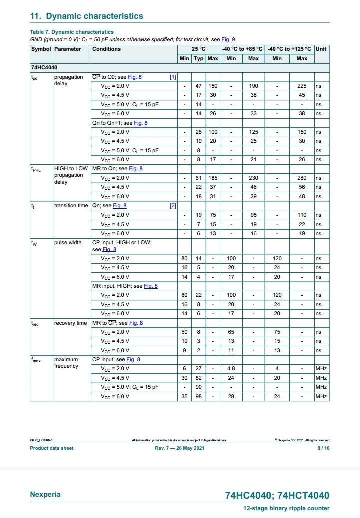
Does 74HC4040 work at 88.5MHz?
I saw a circuit online where FM oscillator's output goes directly to its CLK input.
Just checked datasheet. It says 90MHz.
I'll increase supply to 5.4V. It's also very cheap and still available at $0.2 USD.
11.0592 crystals are all over the web. We been to shift its frequency by +3.3KHz , divide by 16 CD4040, and compared with prescaler signal from 74HC4040 for 88.5MHz VCO out.
12MHz xtal = 96MHz
13.5MHz = 108MHz
Prescaler chips are all smds now. Hobbyist here cannot solder smd parts.
dare4444- Posts : 427
Join date : 2013-03-19
Re: 10mW 4 Channel PLL FM Transmitter
![]() by admin Tue Mar 01, 2022 6:57 am
by admin Tue Mar 01, 2022 6:57 am
dare4444 wrote:Hi Harry,
Even I'm waiting for it to show up on your website. My designs are old and repetitive where as your work is innovative and full of new ideas.
Waiting eagerly
I know, but time is going so fast, and the weeks just flip by. I have a prototype already working, but I have to prove the final design before I can publish.
There was an error on the PCB but I have corrected that: it can be a bit embarrassing to publish something that does not work due to a simple mistake.
The PCB version give more output from the oscillator than the rat's nest, but I have it limited to 100mW. That way it is nice and stable and nothing is pushed to it's limit. Coaxing every last gram of RF can be a balancing act and difficult to reproduce.
BR Harry - SM0VPO
_________________
Everything in this world is either bacon, or it isn't bacon
They say that money cannot bring you happiness, but if you have it then you can always buy more bacon
admin- Admin
- Posts : 1144
Join date : 2012-11-24
Age : 72
Location : Märsta, Sweden -
Re: 10mW 4 Channel PLL FM Transmitter
![]() by dare4444 Mon Feb 28, 2022 11:21 pm
by dare4444 Mon Feb 28, 2022 11:21 pm
Admin wrote:Hi again Joy,
Really interesting circuit. I have just designed a 144MHz > 14MHz transverter and the oscillator is very similar to your design, but I inject 100mW.
AF
|
|
VCO > MB501 > CD4046 < CD4040 < 8MHz Crystal
| V
|______filter______|
The VCO is (by definition) a frequency modulator, so it can be used in the synthesizer or a free-running VCO + 100mW PA.
I hope to poste the new project shortly, but there will be variation on it for other projects.
BR Harry
Hi Harry,
Even I'm waiting for it to show up on your website. My designs are old and repetitive where as your work is innovative and full of new ideas.
Waiting eagerly
dare4444- Posts : 427
Join date : 2013-03-19
admin likes this post
Re: 10mW 4 Channel PLL FM Transmitter
![]() by admin Mon Feb 28, 2022 10:06 pm
by admin Mon Feb 28, 2022 10:06 pm
Really interesting circuit. I have just designed a 144MHz > 14MHz transverter and the oscillator is very similar to your design, but I inject 100mW.
AF
|
|
VCO > MB501 > CD4046 < CD4040 < 8MHz Crystal
| V
|______filter______|
The VCO is (by definition) a frequency modulator, so it can be used in the synthesizer or a free-running VCO + 100mW PA.
I hope to poste the new project shortly, but there will be variation on it for other projects.
BR Harry
_________________
Everything in this world is either bacon, or it isn't bacon
They say that money cannot bring you happiness, but if you have it then you can always buy more bacon
admin- Admin
- Posts : 1144
Join date : 2012-11-24
Age : 72
Location : Märsta, Sweden -
10mW 4 Channel PLL FM Transmitter
![]() by dare4444 Mon Feb 28, 2022 6:38 am
by dare4444 Mon Feb 28, 2022 6:38 am
Use two bit switches connected to IC3 to switch between /64 and /128 divider ate.
CD4040 is a better alternative to IC3 as CD4060 may not work. In my prototype IC3 worked fine.
...
Last edited by dare4444 on Sat Jun 18, 2022 9:01 pm; edited 1 time in total
dare4444- Posts : 427
Join date : 2013-03-19
admin and dare4444 like this post